The Universal Flight Simulator

Phil Smith

Donator
Donator
Joined
Jun 5, 2011
Messages
287
Reaction score
118
Points
58
Location
UK
Hey guys,


Just a brief update on what’s going on with the sim.

I’ve been still on it but moving very slowly; amount of overall work is insane! Haha

Due to complexity of the project and organization proposes I had to come up with numbering system for parts, assemblies, sub-assemblies, drawings, schematics, etc. This task alone took me a month or there abouts lol

Sounds a bit overkill, but it helps a long way to have all your stuff documented.

The list of assemblies which are in design/prototyping/manufacturing process is as follows:
  1. Primary MFD (24’’ 16:10 LCD) – Almost flighty ready! :) Little cosmetic bits and bobs are left to do (e.g. painting some parts, etc.), but all electronics, wiring, etc. are finished.
  2. 2x Auxiliary MFDs (10’’ 16:10 LCD) – Main bezel and button wiring are completed. Control module is under development (enclosure/pcbs/wiring).
  3. Rotational hand controller – All mechanical parts and internal wiring are completed. A bellow hand grip and main enclosure to be designed and printed.
  4. Fuel quantity indicator (4’’ square LCD) – Structural parts are finished; design of power supply PCB and wiring are under way.

I’ve decided now not to start any new component design until all those 4x above are finished 😊

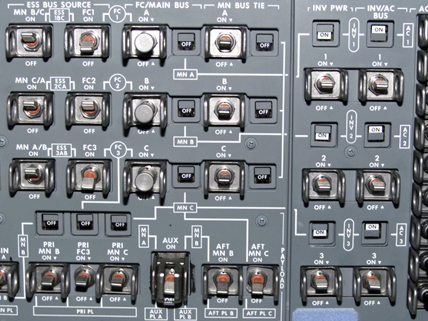
See some pictures are enclosed.

See ya!
 

Attachments

  • 01.jpg
    01.jpg
    109.8 KB · Views: 8
  • 02.jpg
    02.jpg
    97.1 KB · Views: 7
  • 03.jpg
    03.jpg
    89 KB · Views: 7
  • 04.jpg
    04.jpg
    62.6 KB · Views: 7
  • 05.jpg
    05.jpg
    94.6 KB · Views: 6
  • 06.jpg
    06.jpg
    84 KB · Views: 7
  • 07.jpg
    07.jpg
    122.6 KB · Views: 7
  • 08.jpg
    08.jpg
    28.1 KB · Views: 7
  • 09.jpg
    09.jpg
    30.7 KB · Views: 8
  • 10.jpg
    10.jpg
    30.7 KB · Views: 9

Phil Smith

Donator
Donator
Joined
Jun 5, 2011
Messages
287
Reaction score
118
Points
58
Location
UK
Hey guys,

I started thinking of writing weekly progress reports, even if there not so much to say about 😊 This will keep me on track + give you updates and some WIP shots.
Here we go.

Progress report 2024-W16:
  1. Fuel indicator 4x function buttons are done. Actuation force is 8-10N, travel distance - 3mm.
  2. Power supply board (E21613001 A100) for fuel indicator is finished and tested.
  3. Internal harness for fuel indicator is partially wired.
  4. Fuel indicator LCD panel and Raspberry Pi (w/o SD card installed) are powered for the first time from single +12VDC source thru PSU board E21613001 A100.
  5. All 4x boards for 2x 10’’ AUX MFD are etched and tinned.
  6. Via soldering is finished on 2x out of 4x of those AUX MFD boards.
 

Attachments

  • 04.jpg
    04.jpg
    116.9 KB · Views: 7
  • 03.jpg
    03.jpg
    87.1 KB · Views: 9
  • 02.jpg
    02.jpg
    81.2 KB · Views: 7
  • 01.jpg
    01.jpg
    142.4 KB · Views: 8
Last edited:

Phil Smith

Donator
Donator
Joined
Jun 5, 2011
Messages
287
Reaction score
118
Points
58
Location
UK
Morning all,

Progress report 2024-W17:
  1. 90% of internal AMFD wiring for both units are finished. Main cannon connector is universal between all three MFDs, thus the same test harness can be used.
  2. Power supply boards are 95% finished (flux cleaning req'ed) and mounted on corresponding back plates for testing (DC-DC Converter which is under the board is screwed down to the back plate.
  3. Carrier board for raspberry pie are ordered from China and due to delivery next week (All three MFDs share the same board).
  4. The design of an AMFD control module enclosure is finished, 1 item is printed already. 2nd one is due to finish printing today.

As usual, some WIP pictures are attached.

Have a nice week :)
 

Attachments

  • 07.jpg
    07.jpg
    95.6 KB · Views: 6
  • 06.jpg
    06.jpg
    117.3 KB · Views: 7
  • 05.jpg
    05.jpg
    83.4 KB · Views: 8
  • 04.jpg
    04.jpg
    137.1 KB · Views: 8
  • 03.jpg
    03.jpg
    138.9 KB · Views: 8
  • 02.jpg
    02.jpg
    135.2 KB · Views: 6
  • 01.jpg
    01.jpg
    112.6 KB · Views: 6

Phil Smith

Donator
Donator
Joined
Jun 5, 2011
Messages
287
Reaction score
118
Points
58
Location
UK
Little look behind the scenes (Mind you, I've cleaned most of the desk prior taking that picture haha)
 

Attachments

  • 08.jpg
    08.jpg
    101.1 KB · Views: 11

Donamy

Addon Developer
Addon Developer
Donator
Beta Tester
Joined
Oct 16, 2007
Messages
6,927
Reaction score
233
Points
138
Location
Cape
Have you made a translation controller ?
 

Phil Smith

Donator
Donator
Joined
Jun 5, 2011
Messages
287
Reaction score
118
Points
58
Location
UK
Have you made a translation controller ?
Not yet, but I do plan to build it. The CAD model is 75% ready (I'll post a snapshot when get back home). I've decided to finish those instruments first before undertaking any next endeavours haha
 
Last edited:

Phil Smith

Donator
Donator
Joined
Jun 5, 2011
Messages
287
Reaction score
118
Points
58
Location
UK
Have you made a translation controller ?
Here are couple of screenshots of the controller. 75% I stated above was wishful thinking lol Real progress is about 50-60 percent or thereabouts. Haven't touched the model for couple of years for sure...
 

Attachments

  • Translation 01.png
    Translation 01.png
    370.6 KB · Views: 10
  • Translation 02.png
    Translation 02.png
    337.2 KB · Views: 10

Phil Smith

Donator
Donator
Joined
Jun 5, 2011
Messages
287
Reaction score
118
Points
58
Location
UK
Looks great. I'd buy one. ;)
Haha, thanks mate :)
I'm not sure about making them commercially (at least for now), but I can provide files for DIY when it's finished and tested.
 

Phil Smith

Donator
Donator
Joined
Jun 5, 2011
Messages
287
Reaction score
118
Points
58
Location
UK
Hey guys,

Having one extra day off last Monday due to Bank holiday was good for overall progress of the sim :)

Progress report 2024-W18:
1) Both 10'' AMFDs are finished both electrically and mechanically at 95% - I'm waiting for PCBs to arrive from China and 2x JST connectors to complete those 2x units.
2) Fuel quantity indicator is finished. The only thing left is outer casing (which is being printing).
 

Attachments

  • 10.jpg
    10.jpg
    82.5 KB · Views: 6
  • 09.jpg
    09.jpg
    77.1 KB · Views: 6
  • 08.jpg
    08.jpg
    82.3 KB · Views: 6
  • 07.jpg
    07.jpg
    65.2 KB · Views: 7
  • 06.jpg
    06.jpg
    43.3 KB · Views: 7
  • 05.jpg
    05.jpg
    33.5 KB · Views: 7
  • 04.jpg
    04.jpg
    85.6 KB · Views: 5
  • 03.jpg
    03.jpg
    72.4 KB · Views: 6
  • 02.jpg
    02.jpg
    107.2 KB · Views: 6
  • 01.jpg
    01.jpg
    113.7 KB · Views: 7

Phil Smith

Donator
Donator
Joined
Jun 5, 2011
Messages
287
Reaction score
118
Points
58
Location
UK
Afternoon everyone,

Progress report 2024-W19:
  1. Raspberry pi adapter PCBs (E2160001) are arrived from China last week (it is a common board across all 3x MFDs), soldering of components is completed.
  2. Internal wiring and cable management of 10’’ AMFDs are finished (except GPIO wiring).
  3. All 4x instruments (1x PMFD, 2x AMFD, Fuel quantity indicator) have been tested as follows:
  • Power supply test.
  • LCD panel test.
  • Raspberry Pi test.
  • Bezel buttons test.
  • Ethernet cable / main cannon connector test.
All articles are passed all test and can be considered as finished units (painting and some minor cosmetic work req’ed).
 

Attachments

  • 01.jpg
    01.jpg
    109.6 KB · Views: 7
  • 03.jpg
    03.jpg
    100.8 KB · Views: 6
  • 04.jpg
    04.jpg
    72.8 KB · Views: 6
  • 02.jpg
    02.jpg
    93.7 KB · Views: 6
Last edited:

Phil Smith

Donator
Donator
Joined
Jun 5, 2011
Messages
287
Reaction score
118
Points
58
Location
UK
Hey guys,

Progress report 2024-W20:
1) A cumstom heatsink (2611-0010) was manufactured for A100 board (PMFD PSU board).
2) GPIO wiring for PMFD is complete.
3) Reverse ingineeing orocess starded to study force/feeling mechanics of EATON 584 switch. It all comes down to a small assembly with 2x leaf and 2x compression springs (fig. 09). All sheet metal parts have thinkness of 0.4mm. Typical actuation force - 3.75 lbf / 17 N.
 

Attachments

  • 01.jpg
    01.jpg
    53.4 KB · Views: 5
  • 02.jpg
    02.jpg
    52.2 KB · Views: 5
  • 03.jpg
    03.jpg
    120.7 KB · Views: 5
  • 04.jpg
    04.jpg
    181.5 KB · Views: 7
  • 05.jpg
    05.jpg
    122.1 KB · Views: 7
  • 06.jpg
    06.jpg
    103.1 KB · Views: 7
  • 07.jpg
    07.jpg
    100.7 KB · Views: 5
  • 08.jpg
    08.jpg
    119.2 KB · Views: 4
  • 09.jpg
    09.jpg
    90.8 KB · Views: 4
  • 10.jpg
    10.jpg
    39.4 KB · Views: 4

Phil Smith

Donator
Donator
Joined
Jun 5, 2011
Messages
287
Reaction score
118
Points
58
Location
UK
Hey guys,

Progress report 2024-W21:
  1. Enclosure for fuel indicator is printed. Ready for paint.
  2. Modelling rev. C of the Main instrument panel is started. The structure itself is planned to be self-contained with several cannon connectors in the back.

My main inspiration for this one is Buran shuttle’s main panel. I’ll attach couple photos of the real deal in my next post.
It is a quiet simple and elegant solution (yet effective) and very easy to replicate something similar “at home”.
 

Attachments

  • 01.jpg
    01.jpg
    46.4 KB · Views: 4
  • 03.jpg
    03.jpg
    79.4 KB · Views: 3
  • 02.jpg
    02.jpg
    74.5 KB · Views: 4

Phil Smith

Donator
Donator
Joined
Jun 5, 2011
Messages
287
Reaction score
118
Points
58
Location
UK
Some photos of real Buran's main panel without instruments + couple of bonus shots.
I got A LOT of them in my archives - feel free to contact me if you need any reference.

If you got similar photos of Space Shutte – PLEASE let me know. I could not find any yet..
 

Attachments

  • Buran stripped cockpit 04.jpg
    Buran stripped cockpit 04.jpg
    93.5 KB · Views: 5
  • Buran stripped cockpit 03.jpg
    Buran stripped cockpit 03.jpg
    141.3 KB · Views: 6
  • Buran cockpit 01.jpg
    Buran cockpit 01.jpg
    121.1 KB · Views: 4
  • 13.png
    13.png
    755.7 KB · Views: 4
  • 5051832c5d8e.jpg
    5051832c5d8e.jpg
    79.4 KB · Views: 6
  • 3007534e5fa7.jpg
    3007534e5fa7.jpg
    95.4 KB · Views: 6
  • 13e4fe48e0c8.jpg
    13e4fe48e0c8.jpg
    81.5 KB · Views: 6
  • 8b09440c78f9.jpg
    8b09440c78f9.jpg
    117.9 KB · Views: 6
  • 5ef13b8383e9.jpg
    5ef13b8383e9.jpg
    97.1 KB · Views: 6
  • 0d5abc64cd4b.jpg
    0d5abc64cd4b.jpg
    85.8 KB · Views: 5

TheShuttleExperience

Well-known member
Joined
Feb 24, 2021
Messages
994
Reaction score
1,249
Points
108
Location
Earth
If you got similar photos of Space Shutte – PLEASE let me know. I could not find any yet..
Here are a few nice closeups for download:


Maybe also useful:


This one includes full screen high quality 360° tours:


👆 great for zooming to literally every corner of the flight deck and middeck to create your own gallery from screenshots. Also includes the cockpit of the Shuttle Training Aircraft on the bottom of the page!
 
Last edited:

Phil Smith

Donator
Donator
Joined
Jun 5, 2011
Messages
287
Reaction score
118
Points
58
Location
UK
Here are a few nice closeups for download:


Maybe also useful:


This one includes full screen high quality 360° tours:


👆 great for zooming to literally every corner of the flight deck and middeck to create your own gallery from screenshots. Also includes the cockpit of the Shuttle Training Aircraft on the bottom of the page!
Thank you for the links, some great info right there! :)

Yes I got a lot shuttle photos like those as well with all inside panels and instruments installed, but never saw stripped down version of crew compartment from the inside during manufacturing, only from outside (see attached).
I've found a shot with removed instrument giving you a small sneak peek view of main instrument panel internal structure.
But I’m pretty sure it is similar to airline designs such as 737 and 747 main instrument panels, photos of which are readily available on the net.
 

Attachments

  • space-shuttle-atlantis-construction-crew-module2.jpg
    space-shuttle-atlantis-construction-crew-module2.jpg
    57.1 KB · Views: 3
  • 7400b28cbecbe424d3e91167ea9d2972.jpg
    7400b28cbecbe424d3e91167ea9d2972.jpg
    155.4 KB · Views: 3
  • 969be31e5caa1fa756fd8859ed981597.jpg
    969be31e5caa1fa756fd8859ed981597.jpg
    108.5 KB · Views: 3
  • Z211.jpg
    Z211.jpg
    21.3 KB · Views: 3
  • space-shuttle-atlantis-construction-fuselage.jpg
    space-shuttle-atlantis-construction-fuselage.jpg
    51.9 KB · Views: 4
  • main-qimg-959ff97616031ee69300ecc796904059-lq.jpg
    main-qimg-959ff97616031ee69300ecc796904059-lq.jpg
    63.4 KB · Views: 4
Top