I've been doing quite a lot of tinkering with the touchdown points model to mimic bouncing balls and buoyant effects for surface vessels. I think there is some general confusion about what the touchdown point model is doing under the hood which makes setting proper contact points a challenge. Since I already was doing experimentation with a simple box mesh I figured I'd illustrate with some examples. Some of this is copy/pasted from my previous posts on the subject just to consolidate the ideas in one place.
The Touchdown Model
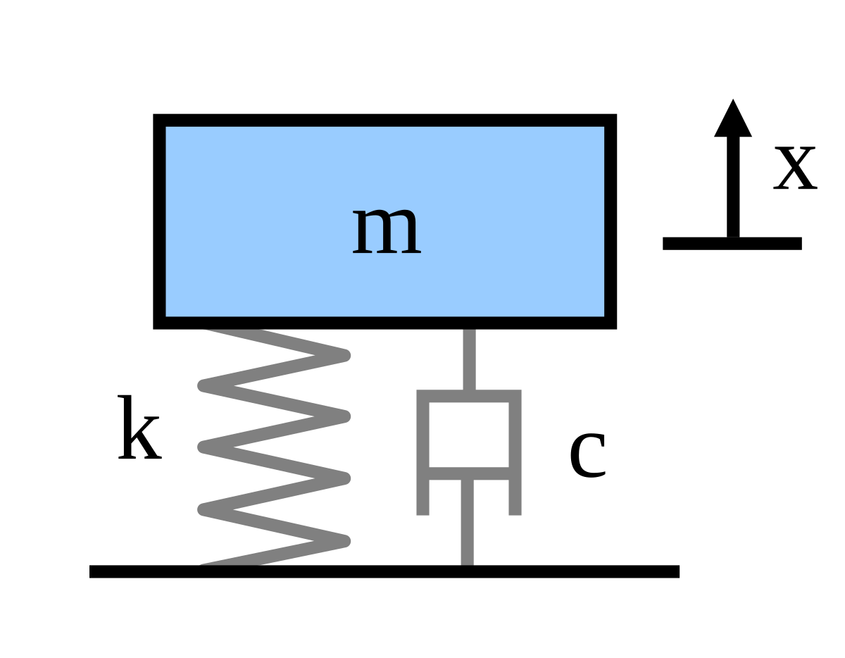
The touchdown model applies a simple forced mass-spring-damper model between a touchdown point on the vessel to a corresponding contact point on the planet surface:[math]my'' + cy' + ky = \sum F_y[/math]
where m is the mass supported by the contact, y is the displacement, y' is the rate of displacement, and y'' is the acceleration. The coefficients are defined as:
Stiffness coefficient (Applied spring force per unit displacement): [math]k = F_S/y[/math]
Damping coefficient (Applied damping force per unit rate of displacement): [math]c = F_D/y'[/math]
So if you have a vessel with n touchdown points all initially at y = 0 (where y is in the local vertical direction opposite gravity), and you specify a vessel weight mg and a stiffness k, the mesh will "sink" until the weight is supported by the springs at a depth y = mg/nk, which looks something like this:

Note that there are dampers in parallel with the springs to dissipate energy, but I've omitted them for clarity to focus on the spring forces. The dampers only oppose motion and don't apply forces in static situations.
Also note that, while the touchdown points are fixed in vessel coordinates, they do not have to be coincident with any part of the mesh. As I'll show below, sometimes that is useful when trying to get a vessel to set properly on a surface.
Setting Touchdown Points
The first thing to note in the figure is that the vessel hangs under the contact points. What this means is, if you specify the contact points to coincide with points on the physical bottom of your mesh, and you have a spring stiffness k anything less than infinity, the bottom of your vessel mesh will fall through the surface until its weight is supported by the springs.
As an example, take the following mesh which is a simple 1 m cube. The origin of the vessel coordinate system is the bottom center of the box.

If one wanted this solid box to rest on the surface as if it were solid, one might intuitively try to put the bottom touchdown points coincident with the bottom four vertices of the mesh (the first four points in the touchdown list):
However, once the simulation starts and you leave a landed condition, the vessel weight will be taken up by the springs until the net applied spring force balances the weight. With the vessel above, that requires a spring displacement of 0.5 m (rather soft springs meant to mimic buoyant forces in water):

So what this means is, if I want the bottom of the mesh to rest on the surface, I need to move the location of the touchdown points to 0.5 m below the mesh (y = -0.5 m) in vessel coordinates like this:
At equilibrium this puts the mesh at the surface:

But note that I say "at equilibrium". This mesh is supported by four springs stretched 0.5 meters. It can bounce on those springs through the surface.
If you wish to model a rigid contact like a landing skid, you will need to increase the stiffness k, so less displacement is needed to support the vessel. However, the stiffer that you make the spring, the higher its vibration frequency becomes. If you don't want any bounce, you need to set the damping value at least to critical damping value or higher.
Procedure to Set Rigid Touchdown Points
So if you want a rigid vessel to sit like a rigid vessel on the surface, here's what you need to do:

And the status of the vessel in (Current State).scn is Landed:
Example: Setting Touchdown Points for VW Thing
So I have made a VW Thing vessel as a simple car to tinker with ground handling models. This is the mesh:

The wheel mesh groups were created in vessel coordinates located where they would be when the suspension is under vehicle weight. So when we establish the touchdown points, we want it to rest as shown in the above picture.
For starters, we'll (temporarily) set the touchdown points to be location of the lowest points of all four wheels in the mesh:
If we assume that the vessel weight is equally distributed on all four wheels (hmm), and assume that the suspension deflection under this weight would be 10 cm (0.1 m or about 4 inches), we could set touchdown points like this:
We expect that when we leave a landed state that the vessel will sink into the ground by travel = 0.1 m. What actually happens is this:

Close, but not quite. It turns out that the vessel weight is not equally supported by the front and rear wheels as the center of mass is closer to the rear wheels. So we need to do a little statics to figure out the weight supported by the front and rear wheels, and if we want the same deflection all around, that means the rear wheel contact points will need to be a bit stiffer than the front. Here is the arrangement with the Z locations of the vessel center of mass and front and rear touchdown points:

For any object there are two requirements for it remain static:
[math]\sum F_y = 0[/math]
[math]F_f + F_r = W[/math]
We need a second equation to solve for the forces, which we get from the moment equation. In theory we could pick any point on the Y-Z plane, but the math simplifies if you pick a point where one of the unknown forces acts, since the moment of that force about that point is 0. I chose to do sum of moments around the rear wheel touchdown point to solve for [imath]F_f[/imath]. Note I am using the right hand rule for moments, but this will work with a left handed convention just as well if Orbiter has burned that system into your skull.
Sum of moments around that point is:
[math]\sum M_r = 0[/math]
Right turning moments = Left turning moments
[math]F_f (z_f - z_r) = W (-z_r)[/math]
[math]F_f = W (-z_r)/(z_f - z_r)[/math]
You can either do sum of moments around the front wheel to get [imath]F_r[/imath] in a similar fashion, or just use sum of forces to get it:
[math]F_r = W - F_f[/math]
I left this in variable form in my code, but we can check our math by putting the numbers in:
[imath] W = mg[/imath] = (1010 kg) (9.81 m/s2) = 9908 N
[imath]F_f = W (-z_r)/(z_f - z_r)[/imath] = 9908 N (+1.084 m)/(1.392 m - (-1.084 m)) = 4338 N
[imath]F_r = W - F_f[/imath] = 9908 N - 4338 N = 5570 N
All the forces are positive as drawn, and the weight supported by the rear wheels [imath]F_r[/imath] is higher than [imath]F_f[/imath], as expected. This procedure can be done as well for more complicated vessels that aren't symmetric by doing these equations in all three coordinate axes.
Since the front and rear wheels support different fractions of the vessel weight, but we want a level vehicle with each touchdown point having the same displacement travel, that means the front and rear contact points must have different stiffness:
Front touchdown point stiffness = 0.5 [imath]F_f/travel[/imath]
Rear touchdown point stiffness = 0.5 [imath]F_r/travel[/imath]
The 0.5 is to account for two wheels supporting the vehicle at front and rear.
So we update our touchdown point stiffness and damping, and I made some body touchdown points for collisions:
Testing this out and calculating the depth of each touchdown point in local coordinates:

The car now sits level, and each touchdown point is hanging 0.1 m below the surface, exactly equal to the specified spring travel.
So now the touchdown points are taking load, but they are 0.1 m below the surface. So like I did with the box, we need to update the touchdown points by lowering the Y height by 0.1 m (-0.322 m to -0.422 m) to get the wheels to rest on the surface:

Perfect!") Notice that the touchdown points are still located at -0.1 m because that is the spring deflection needed to support the vessel, but the mesh is now 0.1 m higher to compensate for that.
Notice that the touchdown points are still located at -0.1 m because that is the spring deflection needed to support the vessel, but the mesh is now 0.1 m higher to compensate for that.
The Touchdown Model
The touchdown model applies a simple forced mass-spring-damper model between a touchdown point on the vessel to a corresponding contact point on the planet surface:[math]my'' + cy' + ky = \sum F_y[/math]
where m is the mass supported by the contact, y is the displacement, y' is the rate of displacement, and y'' is the acceleration. The coefficients are defined as:
Stiffness coefficient (Applied spring force per unit displacement): [math]k = F_S/y[/math]
Damping coefficient (Applied damping force per unit rate of displacement): [math]c = F_D/y'[/math]
So if you have a vessel with n touchdown points all initially at y = 0 (where y is in the local vertical direction opposite gravity), and you specify a vessel weight mg and a stiffness k, the mesh will "sink" until the weight is supported by the springs at a depth y = mg/nk, which looks something like this:
Note that there are dampers in parallel with the springs to dissipate energy, but I've omitted them for clarity to focus on the spring forces. The dampers only oppose motion and don't apply forces in static situations.
Also note that, while the touchdown points are fixed in vessel coordinates, they do not have to be coincident with any part of the mesh. As I'll show below, sometimes that is useful when trying to get a vessel to set properly on a surface.
Setting Touchdown Points
The first thing to note in the figure is that the vessel hangs under the contact points. What this means is, if you specify the contact points to coincide with points on the physical bottom of your mesh, and you have a spring stiffness k anything less than infinity, the bottom of your vessel mesh will fall through the surface until its weight is supported by the springs.
As an example, take the following mesh which is a simple 1 m cube. The origin of the vessel coordinate system is the bottom center of the box.
If one wanted this solid box to rest on the surface as if it were solid, one might intuitively try to put the bottom touchdown points coincident with the bottom four vertices of the mesh (the first four points in the touchdown list):
Code:
stiffness_value = (rho*g)/4

damping_value = math.sqrt(4.0*empty_mass*stiffness_value) --critical damping

mu_value = 0.0

td_points  =
{
     {pos = {x = 0.5, y = 0.0, z = 0.5}, stiffness = stiffness_value, damping = damping_value, mu = mu_value, mu_lng = mu_value},
     {pos = {x = -0.5, y = 0.0, z = 0.5}, stiffness = stiffness_value, damping = damping_value, mu = mu_value, mu_lng = mu_value},
     {pos = {x = 0.5, y = 0.0, z = -0.5}, stiffness = stiffness_value, damping = damping_value, mu = mu_value, mu_lng = mu_value},
     {pos = {x = -0.5, y = 0.0, z = -0.5}, stiffness = stiffness_value, damping = damping_value, mu = mu_value, mu_lng = mu_value},
     {pos = {x = 0.5, y = 1.0, z = 0.5}, stiffness = stiffness_value, damping = damping_value, mu = mu_value, mu_lng = mu_value},
     {pos = {x = -0.5, y = 1.0, z = 0.5}, stiffness = stiffness_value, damping = damping_value, mu = mu_value, mu_lng = mu_value},
     {pos = {x = 0.5, y = 1.0, z = -0.5}, stiffness = stiffness_value, damping = damping_value, mu = mu_value, mu_lng = mu_value},
     {pos = {x = -0.5, y = 1.0, z = -0.5}, stiffness = stiffness_value, damping = damping_value, mu = mu_value, mu_lng = mu_value},

}
vi:set_touchdownpoints(td_points)
However, once the simulation starts and you leave a landed condition, the vessel weight will be taken up by the springs until the net applied spring force balances the weight. With the vessel above, that requires a spring displacement of 0.5 m (rather soft springs meant to mimic buoyant forces in water):
So what this means is, if I want the bottom of the mesh to rest on the surface, I need to move the location of the touchdown points to 0.5 m below the mesh (y = -0.5 m) in vessel coordinates like this:
Code:
td_points_surface  =

{
     {pos = {x = 0.5, y = -0.5, z = 0.5}, stiffness = stiffness_value, damping = damping_value, mu = mu_value, mu_lng = mu_value},
     {pos = {x = -0.5, y = -0.5, z = 0.5}, stiffness = stiffness_value, damping = damping_value, mu = mu_value, mu_lng = mu_value},
     {pos = {x = 0.5, y = -0.5, z = -0.5}, stiffness = stiffness_value, damping = damping_value, mu = mu_value, mu_lng = mu_value},
     {pos = {x = -0.5, y = -0.5, z = -0.5}, stiffness = stiffness_value, damping = damping_value, mu = mu_value, mu_lng = mu_value},
     {pos = {x = 0.5, y = 1.0, z = 0.5}, stiffness = stiffness_value, damping = damping_value, mu = mu_value, mu_lng = mu_value},
     {pos = {x = -0.5, y = 1.0, z = 0.5}, stiffness = stiffness_value, damping = damping_value, mu = mu_value, mu_lng = mu_value},
     {pos = {x = 0.5, y = 1.0, z = -0.5}, stiffness = stiffness_value, damping = damping_value, mu = mu_value, mu_lng = mu_value},
     {pos = {x = -0.5, y = 1.0, z = -0.5}, stiffness = stiffness_value, damping = damping_value, mu = mu_value, mu_lng = mu_value},

}
At equilibrium this puts the mesh at the surface:
But note that I say "at equilibrium". This mesh is supported by four springs stretched 0.5 meters. It can bounce on those springs through the surface.
If you wish to model a rigid contact like a landing skid, you will need to increase the stiffness k, so less displacement is needed to support the vessel. However, the stiffer that you make the spring, the higher its vibration frequency becomes. If you don't want any bounce, you need to set the damping value at least to critical damping value or higher.
Procedure to Set Rigid Touchdown Points
So if you want a rigid vessel to sit like a rigid vessel on the surface, here's what you need to do:
- Determine the mass m and weight W=mg of your vessel under local acceleration of gravity g. Note that the touchdown contact model will provide different displacements on other planets with different local g, so you may need to tune constants for interplanetary operations.
- Determine the amount of spring displacement y under weight load that you would consider "negligible". Zero (0) is not an option here, as that would require a spring stiffness k of infinity. If you are working with a vessel 100s of meters long, fractions of a meter might be "small" to you.
- Determine the number of touchdown points npoints that will be supporting the vessel. Note that this isn't necessarily all of the touchdown points for general vessel collision, just the points that you expect to be touching the surface.
- Determine the fraction of the weight Fw that is supported by each touchdown point. For my simple box, that's pretty easy as the bottom four touchdown points support the full weight, but for vessels with more complex geometry and weight distribution this may not be true. Then you have to do some statics to figure this out for each contact.
- Calculate the stiffness k needed from Fw/y for each touchdown point (note that Fw and y can be different for each and every touchdown point).
- Calculate the critical value of damping [imath]c_c[/imath] needed to dampen any vibration without any overshoot from the critical damping equation [imath]c_c=\sqrt{4mk}[/imath]. You can make it higher, but note that the damper applies a force proportional to rate of displacement. If you crash suddenly you might get yeeted to Alpha Centauri if you make this value too high.
- Set the location of each touchdown point to be y meters below the corresponding contact point on the mesh.
And the status of the vessel in (Current State).scn is Landed:
Code:
BEGIN_SHIPS
Cube:Cube
  STATUS Landed Earth
  POS -80.6825943 28.5969238
  HEADING 330.02
  ALT 0.000
  AROT 66.655 34.068 9.880
  RCSMODE 0
  AFCMODE 7
  PRPLEVEL 0:1.000000
  NAVFREQ 94 524
END
END_SHIPS
Example: Setting Touchdown Points for VW Thing
So I have made a VW Thing vessel as a simple car to tinker with ground handling models. This is the mesh:
The wheel mesh groups were created in vessel coordinates located where they would be when the suspension is under vehicle weight. So when we establish the touchdown points, we want it to rest as shown in the above picture.
For starters, we'll (temporarily) set the touchdown points to be location of the lowest points of all four wheels in the mesh:
Code:
front_right_wheel_contact = {x=0.689 , y=-0.322, z=1.392}
front_left_wheel_contact = {x=-0.689 , y=-0.322, z=1.392}
rear_right_wheel_contact = {x=0.689 , y=-0.322 , z=-1.084}
rear_left_wheel_contact = {x=-0.689 , y=-0.322 , z=-1.084}
If we assume that the vessel weight is equally distributed on all four wheels (hmm), and assume that the suspension deflection under this weight would be 10 cm (0.1 m or about 4 inches), we could set touchdown points like this:
Code:
    travel = 0.1 --suspension travel to support weight of vessel
    stiffness = 0.25*max_weight_front/travel --weight divided over four wheels
    damping = 0.5*math.sqrt(stiffness*empty_mass) --subcritical damping

    td_points =
    {
        {pos=front_right_wheel_contact, stiffness=stiffness, damping=damping, mu=0.0, mu_lng=0.0},
        {pos=front_left_wheel_contact, stiffness=stiffness, damping=damping, mu=0.0, mu_lng=0.0},
        {pos=rear_right_wheel_contact, stiffness=stiffness, damping=damping, mu=0.0, mu_lng=0.0},
        {pos=rear_left_wheel_contact, stiffness=stiffness, damping=damping, mu=0.0, mu_lng=0.0},
        {pos=pt1, stiffness=stiffness, damping=damping, mu=0.2, mu_lng=0.2},
        {pos=pt2, stiffness=stiffness, damping=damping, mu=0.2, mu_lng=0.2},
        {pos=pt3, stiffness=stiffness, damping=damping, mu=0.2, mu_lng=0.2},
        {pos=pt4, stiffness=stiffness, damping=damping, mu=0.2, mu_lng=0.2},
        {pos=pt5, stiffness=stiffness, damping=damping, mu=0.2, mu_lng=0.2},
        {pos=pt6, stiffness=stiffness, damping=damping, mu=0.2, mu_lng=0.2},
        {pos=pt7, stiffness=stiffness, damping=damping, mu=0.2, mu_lng=0.2},
        {pos=pt8, stiffness=stiffness, damping=damping, mu=0.2, mu_lng=0.2}

    }

    vi:set_touchdownpoints(td_points)
We expect that when we leave a landed state that the vessel will sink into the ground by travel = 0.1 m. What actually happens is this:
Close, but not quite. It turns out that the vessel weight is not equally supported by the front and rear wheels as the center of mass is closer to the rear wheels. So we need to do a little statics to figure out the weight supported by the front and rear wheels, and if we want the same deflection all around, that means the rear wheel contact points will need to be a bit stiffer than the front. Here is the arrangement with the Z locations of the vessel center of mass and front and rear touchdown points:
For any object there are two requirements for it remain static:
- Sum of forces on the object in all directions must sum to 0.
- Sum of moments on the object around any point must sum to 0.
[math]\sum F_y = 0[/math]
[math]F_f + F_r = W[/math]
We need a second equation to solve for the forces, which we get from the moment equation. In theory we could pick any point on the Y-Z plane, but the math simplifies if you pick a point where one of the unknown forces acts, since the moment of that force about that point is 0. I chose to do sum of moments around the rear wheel touchdown point to solve for [imath]F_f[/imath]. Note I am using the right hand rule for moments, but this will work with a left handed convention just as well if Orbiter has burned that system into your skull.
Sum of moments around that point is:
[math]\sum M_r = 0[/math]
Right turning moments = Left turning moments
[math]F_f (z_f - z_r) = W (-z_r)[/math]
[math]F_f = W (-z_r)/(z_f - z_r)[/math]
You can either do sum of moments around the front wheel to get [imath]F_r[/imath] in a similar fashion, or just use sum of forces to get it:
[math]F_r = W - F_f[/math]
I left this in variable form in my code, but we can check our math by putting the numbers in:
[imath] W = mg[/imath] = (1010 kg) (9.81 m/s2) = 9908 N
[imath]F_f = W (-z_r)/(z_f - z_r)[/imath] = 9908 N (+1.084 m)/(1.392 m - (-1.084 m)) = 4338 N
[imath]F_r = W - F_f[/imath] = 9908 N - 4338 N = 5570 N
All the forces are positive as drawn, and the weight supported by the rear wheels [imath]F_r[/imath] is higher than [imath]F_f[/imath], as expected. This procedure can be done as well for more complicated vessels that aren't symmetric by doing these equations in all three coordinate axes.
Since the front and rear wheels support different fractions of the vessel weight, but we want a level vehicle with each touchdown point having the same displacement travel, that means the front and rear contact points must have different stiffness:
Front touchdown point stiffness = 0.5 [imath]F_f/travel[/imath]
Rear touchdown point stiffness = 0.5 [imath]F_r/travel[/imath]
The 0.5 is to account for two wheels supporting the vehicle at front and rear.
So we update our touchdown point stiffness and damping, and I made some body touchdown points for collisions:
Code:
     travel = 0.1
     wheel_base = front_right_wheel_contact.z - rear_right_wheel_contact.z
     max_weight_front = max_weight*(-rear_right_wheel_contact.z/wheel_base)  --weight supported by two front wheels.
     max_weight_rear = max_weight - max_weight_front                         --weight supported by two rear wheels.

     front_stiffness = 0.5*max_weight_front/travel
     front_damping = 0.5*math.sqrt(front_stiffness*empty_mass)

     rear_stiffness = 0.5*max_weight_rear/travel
     rear_damping = 0.5*math.sqrt(rear_stiffness*empty_mass)

     body_stiffness = max_weight/travel
     body_damping = math.sqrt(4.0*body_stiffness*empty_mass) --critical damping

     td_points =
     {
         {pos=front_right_wheel_contact, stiffness=front_stiffness, damping=front_damping, mu=0.0, mu_lng=0.0},
         {pos=front_left_wheel_contact, stiffness=front_stiffness, damping=front_damping, mu=0.0, mu_lng=0.0},
         {pos=rear_right_wheel_contact, stiffness=rear_stiffness, damping=rear_damping, mu=0.0, mu_lng=0.0},
         {pos=rear_left_wheel_contact, stiffness=rear_stiffness, damping=rear_damping, mu=0.0, mu_lng=0.0},
         {pos=pt1, stiffness=body_stiffness, damping=body_damping, mu=0.2, mu_lng=0.2},
         {pos=pt2, stiffness=body_stiffness, damping=body_damping, mu=0.2, mu_lng=0.2},
         {pos=pt3, stiffness=body_stiffness, damping=body_damping, mu=0.2, mu_lng=0.2},
         {pos=pt4, stiffness=body_stiffness, damping=body_damping, mu=0.2, mu_lng=0.2},
         {pos=pt5, stiffness=body_stiffness, damping=body_damping, mu=0.2, mu_lng=0.2},
         {pos=pt6, stiffness=body_stiffness, damping=body_damping, mu=0.2, mu_lng=0.2},
         {pos=pt7, stiffness=body_stiffness, damping=body_damping, mu=0.2, mu_lng=0.2},
         {pos=pt8, stiffness=body_stiffness, damping=body_damping, mu=0.2, mu_lng=0.2}
     }

     vi:set_touchdownpoints(td_points)
Testing this out and calculating the depth of each touchdown point in local coordinates:
The car now sits level, and each touchdown point is hanging 0.1 m below the surface, exactly equal to the specified spring travel.
So now the touchdown points are taking load, but they are 0.1 m below the surface. So like I did with the box, we need to update the touchdown points by lowering the Y height by 0.1 m (-0.322 m to -0.422 m) to get the wheels to rest on the surface:
Code:
front_right_wheel_contact = {x=0.689 , y=-0.422, z=1.392}
front_left_wheel_contact = {x=-0.689 , y=-0.422, z=1.392}
rear_right_wheel_contact = {x=0.689 , y=-0.422, z=-1.084}
rear_left_wheel_contact = {x=-0.689 , y=-0.422, z=-1.084}
Perfect!
Notice that the touchdown points are still located at -0.1 m because that is the spring deflection needed to support the vessel, but the mesh is now 0.1 m higher to compensate for that.
Last edited:
 ). Never got much pass the thinking phase... I was waiting for the next cycle of Orbiter development. Also, adding compression limits might make sense, given what a tire or landing gear does in reality.... not sure if it would help or hinder stability though.