Making a wake:

That would be a fun boat! I am sure you would, but make sure that all the exterior hull meshes are separate mesh groups. If possible, if you can limit the number of vertices in the hull to a couple of hundred, that would keep the computational cost sensible.I'll make this one, quite a conventional 2 screws + 1 rudder configuration.

The spinning is actually around the vertical axis of the object, both for the ball and the box meshes, and it happens right as the object hits the water, but if it doesn't get sent into orbit, it generally stabilizes and stops. It really isn't a center of buoyancy stability issue.I don’t know anything about coding, but in the case of a floating boat, typically, the center of gravity is slightly below the center of buoyancy keeping it upright except for wave action. Any symmetrical object such as a ball, usually, since we can’t build anything perfect, one side will be slightly heavier, so that the ball rotates until the heavy side is down. I wonder if, since your faceted ball is mathematically symmetrical, the math gets confused. Maybe if you introduce a very small mass, let’s say 0.5 %or one % of the total mass a couple millimeters off center so the code slowly turns it heavy side down, if the math would work better. I don’t know, just a thought.


That looks great! FYI my Zorb mesh has 290 vertices and it handles the touchdown point hydrostatic model fine. I'd reckon if you can keep the exterior hull vertices under 1000 it should run OK. If you can call out the hull up to the main deck as separate mesh groups that should be fine. If possible, if you can get the locations and vectors defining the rotation axes of the rudders and propellers for animations they should be easy enough to animate.The hull itself is pretty much finished, we now have propellers and a rudder that can be animated, plus some progress on the 'superstructures' :
I'll make a separate mesh of the lower hull so that you'll have something not too crazy for the calculations.
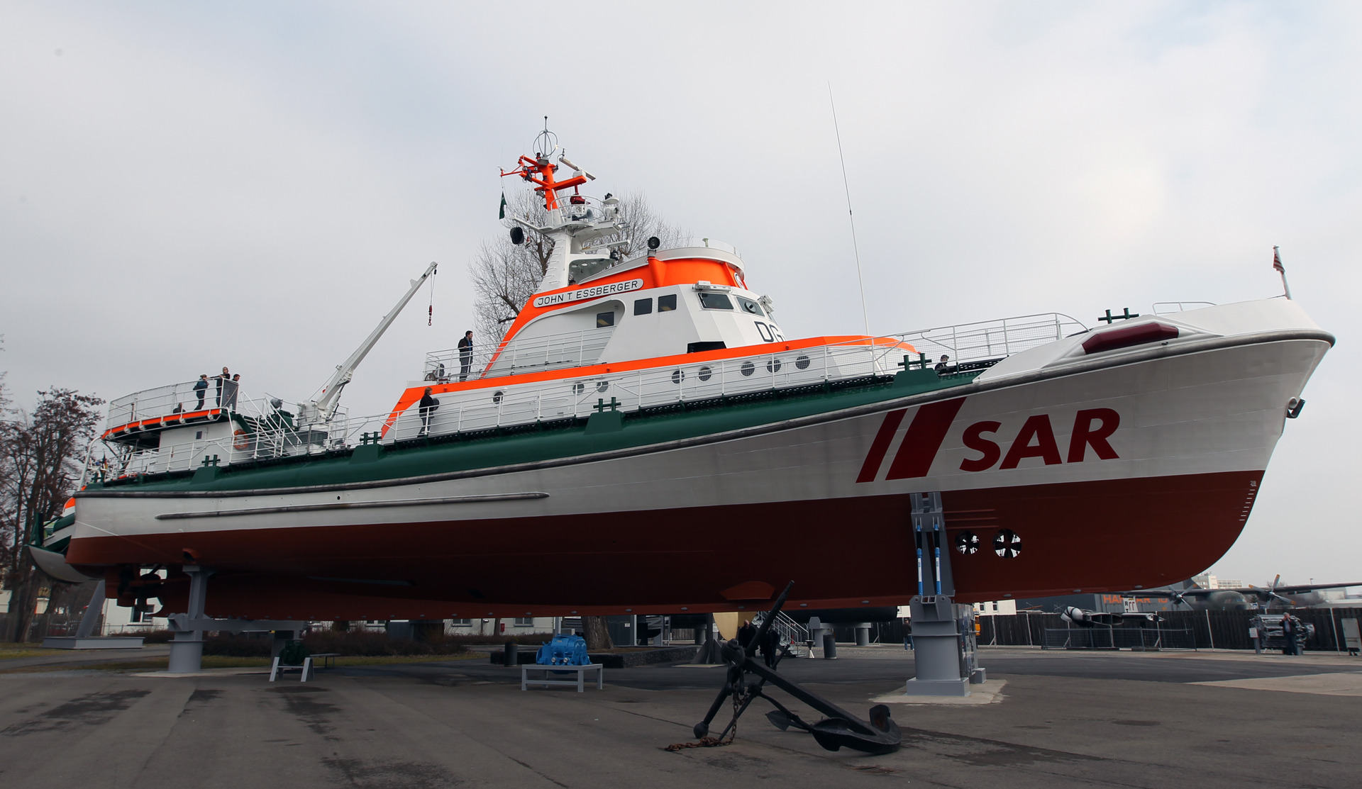
That ship isn't build for high speeds, but it sure can handle rough seas!
View attachment 41365
View attachment 41366
View attachment 41367

That number of hull vertices is quite fine. One concern is the distribution of those vertices. Each touchdown spring essentially is applying a force that is assumed to be average over a small area of the hull around a vertex. If there are large areas of the hull with no vertices like around the midsection where the prop shafts emerge, no forces will be applied there, but if there are a lot of vertices clustered together like at the bow and stern there will be a lot of force concentrated there. It could make for a strange force distribution that won't be physically realistic. Practically you might not be able to do much with the vertices with the mesh. It suggests that maybe I need to decouple the touchdown spring model from the mesh vertices and try to uniformly distribute touchdown points over the hull in some way.This is the part I plan to separate as the 'hull mesh'. It says 127 vertices, you have to multiply that number by 2, because it will be mirrored. So, 254 vertices, we're inside the 'vertices budget'.
I think that the keel should be defined separately as an horizontal stabilizer ? Also maybe the fins-like struts that connect the propeller shafts.
I can also add the propeller shafts as a separate mesh.
View attachment 41371
I wouldn't worry about it. I think the physics must be handled in code, not in the mesh.OK, I can add an edge loop (under the cockpit) in the mid-section, no problem, just let me know.
Yes, that's something I am realizing. I'll have to somehow sample the hull geometry to make a touchdown point "mesh" independent of the visual mesh.Yes, I think that any model that will more or less be drawn after a real hull will have this 'distribution' issue.
I wouldn't worry about it. I think the physics must be handled in code, not in the mesh.
Yes, that's something I am realizing. I'll have to somehow sample the hull geometry to make a touchdown point "mesh" independent of the visual mesh.
Certainly there are many ways to abstract the situation into a model. I'm working on a couple different ones. This method of just modeling the vessel as a basic box and calculating metacenters and moments would certainly work for basic boat-like vessels, and indeed it might be the computationally simplest. But is a 44-ft USCG vessel realistically modeled by a box? If the vessel is very dynamic, determining the metacenters and righting moments of a box is basically the same as integrating the hydrostatic equations on the crudest hull mesh possible. I may try this, but I would have to believe it would suffer from the same stability issues as my more general hydrostatic model (something of a boundary element method vs. FEM).How about the cheapest solution of just scaling an ideal hull model to the mesh? You would then just require length, beam and weight. Maybe also freeboard, if you want to simulate sinking. With an displacement vector, you could also model metacentric height and rightening moment.
Maybe the behaviour is then even reduced to just the forces, no longer needing a FEM.