• ORBITER-FORUM will be temporarily closed at 2026-07-23 18:00 UTC while we complete some OF maintenance tasks. The amount of downtime is expected to take up to one hour, but probably less.

Gaming Car simulation and Orbiter

I believe this is the "Nyquist Frequency".

Similar, but not the same.
The problem addressed by Nyquist is whether a certain frequency can still be represented in a discrete signal. This is not really interesting in this case: vibrations faster than a certain frequency aren't visible anyway, so it doesn't matter if the simulation can't handle them. Stability of the simulation is more important; see for instance this page. It has a nice picture of the problem:
600px-StiffEquationNumericalSolvers.svg.png


I haven't found a mathematical justification, but many people seem to follow rules of thumb like "the step size needs to be at least 5 to 10 times smaller than the smallest time scale in the model". For quantitative engineering purposes (e.g. testing the structural integrity of an airplane design in a computer model), I've even heard they use 100 time steps for one period of the fastest oscillation mode in the model. In the picture above, the Euler method is similar to what I use. Orbiter uses Runge Kutta in many cases, which has the same problem, but less dramatically. The green line in the picture has a step size about 2 times larger than the time scale of the system. With smaller step sizes, the Euler method would also approach the exact solution.
 
Implementing cars into space simulation? now that's some crazy stuff.

That, and no surface is entirely frictionless...
Teflon skates on ice ;) Cf~=0.02 or even less. Though not entirely, too.

cjp: How about using a harmonic oscillator equation? If a process feedback can be approximated linearly (and that's the exact case for car suspension), you'll have an analytic solution for any case of life.
 
We had a consultant who studied integrator stability for real-time racing simulation games. The resulting advice was to use integrator frequencies of around 100 times the maximum frequency of interest for Euler integation, 30 times for a second order method (with the same number of function evaluations as Euler), and 10 times for 4th order Runge-Kutta (RK4). Since RK4 takes 4 times the function evaluations of Euler, the winner for our suspension application was this second order method.

We weren't concerned as much with accuracy, but primarily with stability for reasonable accuracy for car suspension models with stiff racing "tire springs".

The second order method I mentioned is useful for small steps for higher frequencies (like in simulations for flight control algorithms) and doesn't predict the future like RK4 so is also well suited to real world problems with sensors or games with player input. It is optimized for second order problems (e.g.: integrating acceleration to change velocity and position states)

ho2 = h * 0.5;
vn = v + (an * 3.0 - a) * ho2;
pn = p + (vn + v)* ho2;

h = step size,
a,v,p are prior acceleration (the saved state), velocity and position
an,vn,pn are the new acceleration (the single function evaluation), velocity and position

You get second order accuracy with the cost of Euler (plus one saved state).

We ran at 300 Hz for a 2.5 to 3 Hz suspension and 10 Hz tire springs.

Another concern with our racing games when choosing integrators and step sizes was the interaction of the vehicle dynamics and the terrain model. A considerable part of the processing load was in interrogating the ground for each tire. So the integrator frequency had to be choosen to mesh well with the step size we could stand for that part of the algorithm also. The x10 frequency for RK4 was too slow to give the ground resolution we wanted. (The ground points that would be sampled were three times farther apart than for the second order method, which is a long distance at racing speeds.)
 
Now all working...no animation for wheels
2mre7fs.gif
,but nice add...
avrec6.gif


imagesCuz77683.jpg

Nice mesh!
Looks familiar to me, but I've never seen it before in Orbiter before.
You know I'm still looking for a mesh to supply with this add-on?
Would you like to give me this mesh, and give me permission to distribute it with the DLL, with a LGPL-compatible license?
If you want me to work on the animation of the wheels, please make sure the wheels are separated from the body. I don't really know the best approach here: either as separate mesh files, or as something like mesh groups(?).
I think as separate meshes is the easiest. In that case, the origin of each wheel mesh should be in the middle of the wheel. I don't know much about mesh groups, but one issue I can see now is that there is a difference between the equilibrium wheel position without load (as in the config file) and with load (which is probably what you have in a nice-looking mesh).
 
That's not my mesh,I just download it from 3D Warehouse and use for personal use.Sorry don't have any car mesh made by me there for can't redistribute these I have...but you could always contact modeler from 3D Warehouse for permission to use.
 
Can you simulate tracked vehicles with this?
Not very realistically. You can use a mesh with tracks in it, and keep the simulated wheels invisible.

In a real tracked vehicle simulation, the result of steering should probably be to add some traction to some wheels, and add some reversed traction to other wheels. And the wheels shouldn't rotate on steering.

It should not be too difficult to add this to the 'suspension' model. The problem with the current design is that it uses two separate models, so whenever something is added, it needs to be added to two different models, in such a way that both models give approximately the same result. So the current design is very bad when it comes to software maintenance.
 
Maybe to check how is kev solve wheel animation...

[ame="http://www.orbithangar.com/searchid.php?ID=2951"]Lunar Rover Ver4[/ame]
 
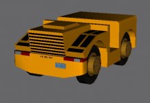
How about a tow vehicle that they use at KSC and Edwards(the Edwards tow-vehicle is white instead of industrial yellow). Should fit the first version just nicely, 4 wheels, forward steering, no real advanced features needed except two attachment points, one forward and one rear.
 

Attachments

  • Tow_vehicle.jpg
    Tow_vehicle.jpg
    66.9 KB · Views: 16
Problem I see with tow vehicles is that they are essentially the tractor in an articulated vehicle. There is a swivel joint between the tow vehicle and the aircraft or trailer being towed, which is more challenging to simulate than a simple payload attachment which fixes the payload to the vehicle body, as with a forklift or a flatbed truck.
 
Back
Top