Project Silent running drones

gattispilot

Addon Developer
Addon Developer
Joined
Oct 17, 2007
Messages
10,659
Reaction score
4,465
Points
203
Location
Dallas, TX
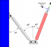
Something I have been playing with. The 3 drones from Silent Running. Not very functional.

The arm extends. I have it coded where the arm fully extends. Has a attachment point where the claw would be if arm extended.

Not sure how to get the attachment point to be where the claw is. That is make the arm extend and retract by degrees. I think I could use SIN and COSINE to figure this out.
Drones1.jpg


DRONE2-1.jpg
 
There is a trick to make Orbiter do the calculations for you.

Code:
static MGROUP_ROTATE MPMAttachment (LOCALVERTEXLIST, MAKEGROUPARRAY(obss_attach_point), 2,
    _V(2.87, 1.90, 3.15), _V(0,0,1), (float)(0.0));

Example from the SSU code. Instead of mesh groups, you can give it an array of VECTOR3 (in this example obss_attach_point, with 2 elements), which will get translated and rotated just like the mesh.

What you just need to remember: The points in the array are positions, not directions. You need to calculate each direction you need between two points.
 
Thank You!

Ever since I forced my girlfriend to watch silent running with me (not a scifi fan at all) she wanted one of those robots. She will be thrilled when I show this to her!
 
I was looking at the RMS code and trying to follow it as it has moveable attachment. One issue is the design of the arm. Unless you unfold the fore arm you can drive the claw into the body.
I was able to move the fore arm and arm in different degrees. But not the attachment point.
 
The design of the arm is completely irrelevant, if you make use of the correct design of your animations.

You only need to have two animations for the last joint of your arm, which both use the same parent.
 
True. I just need to put limitations like if fore arm is not extended then don't do any thing.

The arm is basically 2 parts the arm connected to the body and then the fore arm with the claw. The fore arm is a parent of the arm piece.

BUt it is calculating where the attachment point is. When the arm is stowed it is at one point but has the arm extends the point should change.

try this dlhttp://www.4shared.com/file/70555265/d178e2fa/DRONEZIP.html
 
Last edited:
I don't know what the problem is with animating these...

Look at this quick and dirty drawing and tell me, what is the problem?
 

Attachments

  • SilentRunningArm.png
    SilentRunningArm.png
    41.5 KB · Views: 31
I don't know what the problem is with animating these...

Look at this quick and dirty drawing and tell me, what is the problem?

The arm is animated. Press a key and the forearm extends out and then the rest of the arm. Fore arm extend 180 degrees and the arm part 90 degrees.

It is making the attachment point follow the claw's position
 
It is making the attachment point follow the claw's position

Like I said- just duplicate the final animation component of the arm (which moves the claw) and let the duplicate project the coordinates of the attachment point. Of course, you need to update the parameters of the attachment points in every sim step, the arm moves.
 
I like your hinge on the drawing. Still not sure how to get the attachment point to reflect the degree change. I had the arm the ability to go from 0-90 degrees. So that it would rotate one direction til you press a key, press another key and it would change direction. I had that working for both arms

This is what I have for the code:
Code:
DRONEARM = CreateAttachment (false, _V(-.138,-.001,.76),_V(0,-1,0),_V(0,0,1),"1",false);


if (ARM_status >= ARM_RAISING) {
        double da = simdt * LIFT_SPEED;
        if (ARM_status == ARM_RAISING) {
            if (ARM_proc > 0.0) ARM_proc = max (0.0, ARM_proc-da);
            else                ARM_status = ARM_UP;
        } else {
            if (ARM_proc < 1.0) ARM_proc = min (1.0, ARM_proc+da);
            else                ARM_status = ARM_DOWN;
        }
        SetAnimation (anim_arm01, ARM_proc);
        SetAnimation (anim_arm01a, ARM_proc);
    

}}


void DRONE1::DefineAnimations(void)
{
ANIMATIONCOMPONENT_HANDLE parent;    
    //part1
    static UINT arm_groups1_1[4] = {16,17,23,12};
static MGROUP_ROTATE arm1 (0, arm_groups1_1, 4,_V(-1.09,-.009, .164), _V(-1,0,0), (float)(90*RAD));
anim_arm01 = CreateAnimation (0.0);
parent = AddAnimationComponent (anim_arm01, .5, 1, &arm1);
//part2
static UINT arm_groups1_2[2] = {13,1};//forearm and claw
arm1a = new MGROUP_ROTATE (0, arm_groups1_2, 2,_V(-1.09,-.259,.2), _V(1,0,0), (float)(180*RAD));
anim_arm01a = CreateAnimation (0.0);
parent = AddAnimationComponent (anim_arm01a, 0, .5, arm1a, parent);
 
Last edited:
I like your hinge on the drawing. Still not sure how to get the attachment point to reflect the degree change. I had the arm the ability to go from 0-90 degrees. So that it would rotate one direction til you press a key, press another key and it would change direction. I had that working for both arms

This is what I have for the code:
Code:
DRONEARM = CreateAttachment (false, _V(-.138,-.001,.76),_V(0,-1,0),_V(0,0,1),"1",false);


if (ARM_status >= ARM_RAISING) {
        double da = simdt * LIFT_SPEED;
        if (ARM_status == ARM_RAISING) {
            if (ARM_proc > 0.0) ARM_proc = max (0.0, ARM_proc-da);
            else                ARM_status = ARM_UP;
        } else {
            if (ARM_proc < 1.0) ARM_proc = min (1.0, ARM_proc+da);
            else                ARM_status = ARM_DOWN;
        }
        SetAnimation (anim_arm01, ARM_proc);
        SetAnimation (anim_arm01a, ARM_proc);
    

}}


void DRONE1::DefineAnimations(void)
{
ANIMATIONCOMPONENT_HANDLE parent;    
    //part1
    static UINT arm_groups1_1[4] = {16,17,23,12};
static MGROUP_ROTATE arm1 (0, arm_groups1_1, 4,_V(-1.09,-.009, .164), _V(-1,0,0), (float)(90*RAD));
anim_arm01 = CreateAnimation (0.0);
parent = AddAnimationComponent (anim_arm01, .5, 1, &arm1);
//part2
static UINT arm_groups1_2[2] = {13,1};//forearm and claw
arm1a = new MGROUP_ROTATE (0, arm_groups1_2, 2,_V(-1.09,-.259,.2), _V(1,0,0), (float)(180*RAD));
anim_arm01a = CreateAnimation (0.0);
parent = AddAnimationComponent (anim_arm01a, 0, .5, arm1a, parent);
Here is the code. How should I code the attachment point to move with animation?
 
Do they walk? That could be quite tricky to implement. Looking at the layout, they couldn't lift their feet to step forward, since they are too far from the centre of gravity to balance on a single leg. If I remember correctly, they just shuffled along - but even doing that without falling over could be difficult. Also they seem to be stable only in the lateral, but not in the longitudinal axis. So if they wanted to lift something heavy, they would have to bend backward to counterbalance. I see an interesting mechanics project coming along here ... :)
 
The legs don't move. There are like the UMMU. I don't they could lift much. But it would be nice for the attachment point to follow the arm animations.
 
Change the last line of your code snippet:

Code:
AddAnimationComponent (anim_arm01a, 0, .5, arm1a, parent);
AddAnimationComponent (anim_arm01a, 0, .5, arm1av, parent);


Now, you only need to define the attachment point vertex list:
Code:
arm1a = new MGROUP_ROTATE (0, arm_groups1_2, 2,_V(-1.09,-.259,.2), _V(1,0,0), (float)(180*RAD));
arm1av = new MGROUP_ROTATE (LOCALVERTEXLIST, MAKEGROUPARRAY(iwillunderstandthecodesnippet), before_using_it
,_V(-1.09,-.259,.2), _V(1,0,0), (float)(180*RAD));

 
THanks. I saw this in the SDK:
Instead of adding mesh groups to an animation, it is also possible to add a
local VECTOR3 array. To do this, set “mesh” to LOCALVERTEXLIST, and
set “grp” to MAKEGROUPARRAY(vtxptr), where vtxptr is the VECTOR3
array. “ngrp” is set to the number of vertices in the array. Example:
VECTOR3 vtx[2] = {_V(0,0,0), _V(1,0,-1)};
MGROUP_TRANSFORM *mt = new MGROUP_TRANSFORM (LOCALVERTEXLIST,
MAKEGROUPARRAY(vtx), 2);
AddAnimationComponent (anim, 0, 1, mt);
Transforming local vertices in this way does not have an effect on the visual
appearance of the animation, but it can be used by the module to keep track
of a transformed point during animation. The Atlantis module uses this
method to track a grappled satellite during animation of the RMS arm.

And in RMS code it is used here.

rms_anim[5] = new MGROUP_ROTATE (LOCALVERTEXLIST, MAKEGROUPARRAY(arm_tip), 3,
_V(-2.26,1.7,-6.5), _V(0,0,1), (float)(894*RAD)); // -447 .. +447
anim_arm_wr = CreateAnimation (0.5);
hAC_arm = AddAnimationComponent (anim_arm_wr, 0, 1, rms_anim[5], parent);

and this:
arm_tip[0] = _V(-2.26,1.71,-6.5);
arm_tip[1] = _V(-2.26,1.71,-7.5);
arm_tip[2] = _V(-2.26,2.71,-6.5);

But I don't see in the Atlantis Code where the mesh is set to LOCALVERTEXLIST


Change the last line of your code snippet:

Code:
AddAnimationComponent (anim_arm01a, 0, .5, arm1a, parent);
AddAnimationComponent (anim_arm01a, 0, .5, arm1av, parent);

Now, you only need to define the attachment point vertex list:
Code:
arm1a = new MGROUP_ROTATE (0, arm_groups1_2, 2,_V(-1.09,-.259,.2), _V(1,0,0), (float)(180*RAD));
arm1av = new MGROUP_ROTATE (LOCALVERTEXLIST, MAKEGROUPARRAY(iwillunderstandthecodesnippet), before_using_it
,_V(-1.09,-.259,.2), _V(1,0,0), (float)(180*RAD));
 
You don't set the mesh to LOCALVERTEXLIST. It is a simple constant, defined by the Orbiter API (Reading the API reference can be inspiring ;) ), which tells the animation that it operates on a list of vertexes instead of an array of group indexes.
 
Okay so It looks like this:
arm1a = new MGROUP_ROTATE (0, arm_groups1_2, 2,_V(-1.09,-.259,.2), _V(1,0,0), (float)(180*RAD));
arm1av = new MGROUP_ROTATE (LOCALVERTEXLIST, MAKEGROUPARRAY(claw), 1
,_V(-1.09,-.259,.2), _V(1,0,0), (float)(180*RAD));
claw = _V(-1.09,-.259,.2)//vector3

and the attachment point would be this:
CreateAttachment (false, claw, "G", true);
 
No.

Read the API Reference first. Please.
 
Back
Top