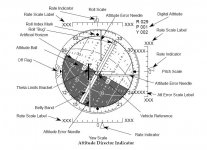
Attitude Director Indicator (ADI)
The ADI gives the crew attitude information as well as attitude rates and errors, which can be read from the position of the pointers and needles. The ADI can be viewed on the Ascent/Entry PFD (A/E PFD), which is a composite of various flight instruments depending upon flight phase, or on the Orbit PFD.
The commanderТs and pilotТs ADIs (supported by IDPs 1, 2, and 3) are supported throughout the mission; the aft ADI (supported by IDP 4) is active only during orbital operations.
The orbiterТs attitude is displayed to the flight crew by a software simulated enclosed ball (sometimes called the eight ball) that is gimbaled to represent three degrees of freedom.
The ball, covered with numbers indicating angle measurements (an implied 0 is added as the last digit of each), moves in response to software-generated commands to depict the current orbiter attitude in terms of pitch, yaw,
and roll.
The wide band dividing the ball represents 0░yaw and is referred to as the belly-band. There is also an artifical horizon representing pitch of 0░, where positive pitch angles (0░ to 180░) are drawn on the white half of the ball and negative pitch angles (180░ to 360░) are drawn on the
darker half of the ball.
In addition to the graphical attitude representation of the ADI ball there is a digital readout to the ADIТs upper-right showing the current roll, pitch, and yaw attitude in degrees.
Each ADI has a set of switches by which the crew can select the mode or scale of the readout.
The commanderТs switches are located on panel F6, the pilotТs on panel F8, and the aft switches on panel A6U.
The ADI ATTITUDE switches determine the unitТs frame of reference: INRTL (inertial), LVLH (local vertical/local horizontal), and REF (reference). The INRTL position allows the flight crew to view the orbiterТs attitude with
respect to the inertial reference frame. The LVLH position shows the orbiterТs attitude from an orbiter-centered rotating reference frame
with respect to Earth. The REF position is primarily used to see the orbiterТs attitude with respect to an inertial reference frame defined when the flight crew last depressed the ATT REF pushbutton above/below the ADI
ATTITUDE switch. The REF position is useful when the crew flies back to a previous attitude or monitors an OMS burn for attitude excursions. On ascent pre-MECO and on entry, with the ADI in LVLH, yaw is not displayed
and the ADI is pinned to the belly-band in yaw. The ADI ATTITUDE switches on panels F6 and F8 are active during ascent, orbital, and transition flight phases. However, they have no effect during entry (MM304, 305, 602, and 603), when the ADI attitude is always shown as LVLH. Also, when the backup flight system (BFS) is engaged, only the commanderТs switches on panel F6 are monitored for configuring both commander and pilot ADIs.
The switch on panel A6U, like the aft ADI, is operational only in orbit.
Each ADI has a set of three rate pointers that provide a continuous readout of vehicle body rotational rates. Roll, pitch, and yaw rates are displayed on the top, right, and bottom pointers, respectively. The center mark on the
scale next to the pointers represents zero rates.
The graduated marks on either side of center indicate positive or negative rates. The ADI RATE switch for each indicator unit determines the magnitude of full-scale deflection. HIGH is the coarsest setting and LOW is the finest setting.
Scaling for each switch position is listed in table A, ADI Rate Switch vs. Full Range Deflection. On the A/E PFD, the rate pointer scales will be labeled
according to the selected scale. The rate scales are not labeled on the Orbit PFD. These pointers are Уfly toФ in the sense that the RHC must be
moved in the same direction as the pointer to null a rate.
ADI rate readings are independent of the selected attitude reference. During ascent, the selected rates come directly from the solid rocket booster or orbiter rate gyro assembly (RGA) sensors to the ADI processor for display
via the rate pointers. During entry, only the RGA selected pitch rate is directly diplayed as the ADI rate. The selected roll and yaw rates are first sent to flight control software, where they are processed and output to the ADI as stability roll and yaw rates. (This transformation is necessary because, in aerodynamic flight, control is achieved about stability axes, which in the cases of roll and yaw differ from body axes.)
In all major modes except TAEM (MM 305 and 603), the rate pointers strictly display vehicle rate information. During TAEM when the ADI
RATE switch is in MED, the ADI rate pointers instead display information on HAC intercept, glideslope error, and crosstrack error, which can
be used to help fly the proper HAC profile.
During TAEM when the ADI RATE switch is in HIGH or LOW, rates will be displayed on a ▒ 5░ per second scale (see table A). The rate scale
labels in TAEM will reflect these changes accordingly.
In addition to the rate pointers, there are three magenta-colored needles on each ADI that display vehicle attitude errors. These error needles extend in front of the ADI ball, with roll, pitch, and yaw arranged in the same
manner as the rate pointers. Similar to the rate pointers, each error needle has an arc-shaped background scale (also magenta) with
graduated marks that allow the flight crew to read the magnitude of the attitude error. The errors are displayed with respect to the body axis coordinate system and, thus, are independent of the selected reference frame of the ADI.
The ADI error needles are driven by flight control outputs that show the difference between the required and current vehicle
attitude. These needles are also Уfly to,Ф meaning that the flight crew must maneuver in the direction of the needle to null the error. For
example, if the pitch error needle is deflected down, the flight crew must manually pitch down to null the pitch attitude error.
The amount of needle deflection, indicating the degree of attitude error, depends upon the position of the ADI ERROR switch for each ADI
and the flight phase. For ascent, orbit, and transition phases, in the HIGH position, full-scale deflection of the error needles represent 10░,
MED represents 5░, and LOW represents 1░. For entry, the needles signify different errors in different phases (see table B). On the A/E PFD
the error scale is also labeled (in magenta) according to ADI ERROR switch position.
On entry during TAEM (MM 305 and 603), a Theta Limits bracket (in green) may be driven overlaying the ADI ball. This is a pitch flying reference (maximum/minimum pitch attitude) when air data transducer assembly (ADTA) data is not available to Guidance and Control (G&C) below Mach 2. This is described in more detail in the TAEM section, 7.4.
The SENSE switch on panel A6U allows the flight crew to use the aft ADI, RHC, and THC in a minus X or minus Z control axis sense. These
two options of the aft ADI and hand controllers correspond to the visual data out of the aft viewing (negative X) or overhead viewing
(negative Z) windows.
Each ADI has a single flag labeled OFF on the left side of the display that is used to indicate whether valid GPC data is driving the ADI software. Presence of the OFF flag can be used to determine if a FC bus problem exists at the
GPC driving the IDP that is hosting the ADI, and is used to help troubleshoot in DPS malfunction procedures.. There are no flags for the rate and error needles; but these indicators are blanked when they are invalid.
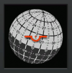
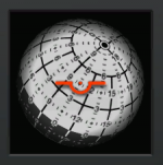
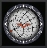
 ) and I was looking for images on the web for inspiration. I came across this page: www.space1.com claiming to show an instrument from a Shuttle simulator. This is essentially the functionality I want to go for, but there is something that confuses me. Check the markings on the ball itself in the first image on the page (frontal view). I thought that the bright/dark hemispheres of the ball are the pitch up/down indicators, the dividing line indicating the horizon. However, in this image it looks like the poles of the ball are on the equator line (altough out of view), rather than at 90 degrees above/below the equator. In other words, the pitch lines don't seem to be circles parallel to the equator, but great circles converging at a point on the equator. Also, the pitch lines are labelled 3 / 0 / 33 instead of 3 / 0 / -3.
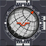
")