You are using an out of date browser. It may not display this or other websites correctly.
You should upgrade or use an alternative browser.
You should upgrade or use an alternative browser.
SSU Development thread (4.0 to 5.0) [DEVELOPMENT HALTED DUE TIME REQUIREMENTS!]
- Thread starter DaveS
- Start date
- Status
- Not open for further replies.
Checked in the updated radiator panels. I kept the mesh group order intact so there's no need for any rebuilds.
It looks much smoother now, thanks!
Finally finished writing the Crawler section for the manual, heavily based on the (now) previous .txt file.
Also finished the windows group, so now they all match the frames and are a plane, so reflections are perfect. (just remembered that I still have to inspect the hatch window... :facepalm")
DaveS, did you finish with the radiators? I noticed some issues that I'd like to fix to tick the rads off the list...
Also finished the windows group, so now they all match the frames and are a plane, so reflections are perfect. (just remembered that I still have to inspect the hatch window... :facepalm
DaveS, did you finish with the radiators? I noticed some issues that I'd like to fix to tick the rads off the list...
- Joined
- Feb 4, 2008
- Messages
- 9,753
- Reaction score
- 1,024
- Points
- 203
Yes, I'm done with them, nothing pending there.DaveS, did you finish with the radiators? I noticed some issues that I'd like to fix to tick the rads off the list...
So I wanted to correct the kinks and waves in the fwd bulkhead, and currently it doesn't match the Xo582 and Xo576 values... it is too forward (also supported by the position of the EVA winch). Also, the "bend" currently does not start at Zo410.
The top of the PLBDs/bulkheads, is it at Zo500 sharp or something else?
The top of the PLBDs/bulkheads, is it at Zo500 sharp or something else?
- Joined
- Feb 4, 2008
- Messages
- 9,753
- Reaction score
- 1,024
- Points
- 203
According to the Payload bay doors and radiator panels familiarization handbook, the PLBDs go from Xo574.090 at the centerline to Xo579.300 at the hinge line at the forward end. The hinge line runs at Zo420 (Zo410 is where the PLB sills are). The top of the doors should be at Zo500.314.
About 2cms fwd at the top, and about 1cm at the bottom.... :facepalm:According to the Payload bay doors and radiator panels familiarization handbook, the PLBDs go from Xo574.090 at the centerline to Xo579.300 at the hinge line at the forward end.
Yes, that is the PLBD hinge line (I started to correct the hinges in a previous rev), but I meant the Zo at which the fwd bulkhead bends.The hinge line runs at Zo420 (Zo410 is where the PLB sills are).
Another ~2cms above where it should be... This also affects the aft compartment, which would now have a lower fwd end, so the OMS pods probably will just need a shift and not a (large) rotation.The top of the doors should be at Zo500.314.
- Joined
- Feb 4, 2008
- Messages
- 9,753
- Reaction score
- 1,024
- Points
- 203
The hinge line is even at Zo420, no matter where you measure it, it's a straight shot from Xo574.090 to Xo1307. The bottom of the doors are Zo420 which is where the midbody ends in the Z-axis. The two bulkheads belong to the forward and aft fuselages respectively. The midbody is an open structure, save for the floor and sidewalls (to which the tiles are bonded).Yes, that is the PLBD hinge line (I started to correct the hinges in a previous rev), but I meant the Zo at which the fwd bulkhead bends.
Finally had time to start correcting the fwd bulkhead, and got it to be much "lighter" and now planar (with the bend)... but I'm not sure the bottom is at the correct place, which apparently should be Xo582. That, the PLBD numbers in the posts above and the bend in the fwd bulkhead at Zo410, can't all be correct... :facepalm:
Anyway, that got me looking at the PLB ring frames, and they are all 6-8cms too forward... this is going to take a while... :uhh:
Anyway, that got me looking at the PLB ring frames, and they are all 6-8cms too forward... this is going to take a while... :uhh:
- Joined
- Feb 4, 2008
- Messages
- 9,753
- Reaction score
- 1,024
- Points
- 203
The angle of the bulkhead begins at Zo420, not Zo410. There's no angle until the PLBD hinge line and all of the hinges are on a perfectly straight line.Finally had time to start correcting the fwd bulkhead, and got it to be much "lighter" and now planar (with the bend)... but I'm not sure the bottom is at the correct place, which apparently should be Xo582. That, the PLBD numbers in the posts above and the bend in the fwd bulkhead at Zo410, can't all be correct...
I've attached a schematic of the midbody showing how both the forward and aft ends are perfectly vertical.
Attachments
I'm considering that as a possibility, but that would "make things even worse", as this: "Xo579.300 at the hinge line" doesn't match the Xo582 of the bottom end of the bulkhead. :shrug:The angle of the bulkhead begins at Zo420, not Zo410. There's no angle until the PLBD hinge line and all of the hinges are on a perfectly straight line.
Those PLBD numbers also don't connect with the position of the fwd winch.
The schematic also has "APPROXIMATE ONLY"....I've attached a schematic of the midbody showing how both the forward and aft ends are perfectly vertical.
- Joined
- Feb 4, 2008
- Messages
- 9,753
- Reaction score
- 1,024
- Points
- 203
The Xo582 point is where the forward attachment for the Bay 1 bridge longeron panels are located. The best I can estimate is that they're approx. 3" in diameter. There's two attach points on each ring frame, and one on the sill longerons. So it is a three-point attachment system, except for Bay 13 which only has two attachment points, forward and top.I'm considering that as a possibility, but that would "make things even worse", as this: "Xo579.300 at the hinge line" doesn't match the Xo582 of the bottom end of the bulkhead.
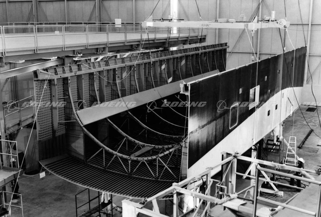
I've attached a photo of the lower fuselage and midbody of an orbiter still being two separate elements, yet close enough to see that there's a perfect vertical line until the PLBD hinge line.The schematic also has "APPROXIMATE ONLY"....
https://www.dropbox.com/s/vm9p5q0begf9kqk/A820617L-93c.JPG?dl=0
On the starboard side of the visible bulkhead "frame", part of the lower fuselage, we can see the bend starting (just where the white bar is secured). Can't tell exactly where that is, but looking at the midbody right behind, a tilted section is visible.I've attached a photo of the lower fuselage and midbody of an orbiter still being two separate elements, yet close enough to see that there's a perfect vertical line until the PLBD hinge line.
https://www.dropbox.com/s/vm9p5q0begf9kqk/A820617L-93c.JPG?dl=0
Same in here (hope the link works):
- Joined
- Feb 4, 2008
- Messages
- 9,753
- Reaction score
- 1,024
- Points
- 203
I think this photo shows it quite clearly, that there's no bend: https://www.dropbox.com/s/gbjzbv2owcdwd87/19830809_1.jpg?dl=0
And this one: https://www.dropbox.com/s/c4j4jzsk62m5sng/OV_midbody.jpg?dl=0
And I now just found this: https://onedrive.live.com/?id=C1A7E9824022AD17!835&cid=C1A7E9824022AD17
And this one: https://www.dropbox.com/s/c4j4jzsk62m5sng/OV_midbody.jpg?dl=0
And I now just found this: https://onedrive.live.com/?id=C1A7E9824022AD17!835&cid=C1A7E9824022AD17
Last edited:
To me it seems there is a bend starting at Zo410, on both images.... :shrug:I think this photo shows it quite clearly, that there's no bend: https://www.dropbox.com/s/gbjzbv2owcdwd87/19830809_1.jpg?dl=0
And this one: https://www.dropbox.com/s/c4j4jzsk62m5sng/OV_midbody.jpg?dl=0
Maybe we need another set of eyes.
I'll go over this when I get home.And I now just found this: https://onedrive.live.com/?id=C1A7E9824022AD17!835&cid=C1A7E9824022AD17
- Joined
- Feb 4, 2008
- Messages
- 9,753
- Reaction score
- 1,024
- Points
- 203
This is the relevant schematic for the midbody: https://onedrive.live.com/?cid=C1A7...22AD17!842&parId=C1A7E9824022AD17!835&o=OneUpI'll go over this when I get home.
This is the relevant schematic for the midbody: https://onedrive.live.com/?cid=C1A7...22AD17!842&parId=C1A7E9824022AD17!835&o=OneUp
I don't know how much stock we can put in a document that has a different vehicle configuration... as far as I can see, none of the schematics show any bend at all.
- Joined
- Feb 4, 2008
- Messages
- 9,753
- Reaction score
- 1,024
- Points
- 203
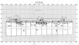
I've attached a colorized example from the SODB of the left profile that shows the internal structural members. Teal vertical line is the lower half of the Xo576 bulkhead, green horizontal line is the PLBD hinge line at Zo420 while the red angled line is the upper half of the Xo576 bulkhead.I don't know how much stock we can put in a document that has a different vehicle configuration... as far as I can see, none of the schematics show any bend at all.
That's as official as it gets, unless we get the actual manufacturing drawings from Convair (the sub-contractor for the mid body, they subsequently merged with General Dynamics which got bought by Lockheed Martin).
Attachments
I've attached a colorized example from the SODB of the left profile that shows the internal structural members. Teal vertical line is the lower half of the Xo576 bulkhead, green horizontal line is the PLBD hinge line at Zo420 while the red angled line is the upper half of the Xo576 bulkhead.
That's as official as it gets, unless we get the actual manufacturing drawings from Convair (the sub-contractor for the mid body, they subsequently merged with General Dynamics which got bought by Lockheed Martin).
That made me laugh... :rofl:
At best, that's a general overview. Most likely we'll never see "the good stuff", i.e., specs for manufacturing, complete with tolerances. Having those would take the fun out of this. :lol:
BTW, the Zo410 number comes from diagram 19.1-2 in JSC-11174. I still haven't seen any numeric reference to Zo420 for this.
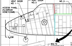
Anyway, found an interesting image that seems to indicate that the PLBDs go a bit forward of the top of the bulkhead, thus the top of the bulkhead is aft of the fwd end of the PLBDs... just don't know how much... :facepalm:
EDIT: Oh, I forgot to post the image:

- Joined
- Feb 4, 2008
- Messages
- 9,753
- Reaction score
- 1,024
- Points
- 203
The indentation you see there on the upper forward fuselage half is the channel for the "monkey fur" and the bulb seal. The bulb seal has a semi-cylindrical seal Teflon outer coating with a CRES spring interior. The bulb seal is responsible for contamination control of the payload bay when the doors are closed and latched. The "monkey fur" is an additional barrier against contamination of the PLB, made of S-glass fibers which give it the furry appearance. The fibers are coated in an icephobic material which has the nickname of "monkey fur coating". There's similar channels for the bulb seal/monkey fur in the top parts of the PLB sill longerons.EDIT: Oh, I forgot to post the image:
Edit:
JSC-11174 Vol II. page 225 clearly shows centerline of the hinges at Zo420. Yo is +/-106.28.
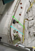
I've have attached a photo of the Xo576 bulkhead on Endeavour showing the bulb seal (teal arrow) and the monkey fur (green arrow).
Attachments
Last edited:
- Status
- Not open for further replies.
Similar threads
- Replies
- 12
- Views
- 3K
- Replies
- 137
- Views
- 22K
- Replies
- 143
- Views
- 34K
- Replies
- 21
- Views
- 18K