What makes you think the PLBD hinge has anything to do with the fwd bulkhead?JSC-11174 Vol II. page 225 clearly shows centerline of the hinges at Zo420. Yo is +/-106.28.
You are using an out of date browser. It may not display this or other websites correctly.
You should upgrade or use an alternative browser.
You should upgrade or use an alternative browser.
SSU Development thread (4.0 to 5.0) [DEVELOPMENT HALTED DUE TIME REQUIREMENTS!]
- Thread starter DaveS
- Start date
- Status
- Not open for further replies.
- Joined
- Feb 4, 2008
- Messages
- 9,753
- Reaction score
- 1,024
- Points
- 203
Because that's the angle begins, if we're talking about the same thing which should be the the angle of the Xo576 bulkhead (BTW, that designation derives from the center point of the bulkhead which is at Xo576.695 when taking account the angled upper section).What makes you think the PLBD hinge has anything to do with the fwd bulkhead?
Because that's the angle begins, if we're talking about the same thing which should be the the angle of the Xo576 bulkhead (BTW, that designation derives from the center point of the bulkhead which is at Xo576.695 when taking account the angled upper section).
Can you make a sketch of the side view of the area, with the all the relevant points (only "hard" data, no estimations from diagrams), to see if things line up? No need to rush, as correcting the PLB ring frame will take time.
Initially I also thought the bend started at Zo420, but the only available data, and photos, point to Zo410, so unless it works with 420 and not with 410, it's going to be 410. :shrug:
- Joined
- Feb 4, 2008
- Messages
- 9,753
- Reaction score
- 1,024
- Points
- 203
How about this: Each of the four sling attachment points on the orbiter are located at the join lines of each fuselage section. The two forward attachment points are located at the join between the forward fuselage and the midbody. The aft attachment points are located at the join lines of the midbody and the aft engine compartment. This is to ensure that no one section has to take the entire load by itself by distributing it to other sections.Can you make a sketch of the side view of the area, with the all the relevant points (only "hard" data, no estimations from diagrams), to see if things line up? No need to rush, as correcting the PLB ring frame will take time.
I've attached a photo of Endeavour showing how the forward sling attachment point on the left side intersects the lower point of the PLBD perfectly.
Attachments

Last edited:
The attachments can be in a zone where parts connect, as those already have more structure, thus saving weight. It doesn't mean that the attachment is exactly in the middle of the joint.How about this: Each of the four sling attachment points on the orbiter are located at the join lines of each fuselage section. The two forward attachment points are located at the join between the forward fuselage and the midbody. The aft attachment points are located at the join lines of the midbody and the aft engine compartment. This is to ensure that no one section has to take the entire load by itself by distributing it to other sections.
That's a line connecting 2 points, nothing more. A straight line connecting 3 points would prove something.I've attached a photo of Endeavour showing how the forward sling attachment point on the left side intersects the lower point of the PLBD perfectly.
All this back-and-forth is not nought as things will only fit in one way. Making a diagram with the available data only, will quickly show if the bend is at Zo410, at 420 or somewhere else.
- Joined
- Feb 4, 2008
- Messages
- 9,753
- Reaction score
- 1,024
- Points
- 203
This is the best photo that I have found that shows the midbody from a side angle, it is the midbody for OV-103 being delivered to Rockwell Intl. The structure is upside down (this is how it was transported) and forward is to the left in the photo, away from the truck.
https://www.dropbox.com/s/zmogp0xme7okfc4/A820316L-6c.jpg?dl=0
---------- Post added at 05:35 PM ---------- Previous post was at 01:23 PM ----------
What bout this photo: https://secure.boeingimages.com/arc...owered-into-Forward-Fuselage-2F3XC5HUEW3.html
You can clearly see the aft edge of the lower forward fuselage half and it looks pretty darn vertical to me.
This is the best photo that I have found that shows the midbody from a side angle, it is the midbody for OV-103 being delivered to Rockwell Intl. The structure is upside down (this is how it was transported) and forward is to the left in the photo, away from the truck.
https://www.dropbox.com/s/zmogp0xme7okfc4/A820316L-6c.jpg?dl=0
---------- Post added at 05:35 PM ---------- Previous post was at 01:23 PM ----------
What bout this photo: https://secure.boeingimages.com/arc...owered-into-Forward-Fuselage-2F3XC5HUEW3.html
You can clearly see the aft edge of the lower forward fuselage half and it looks pretty darn vertical to me.
The first one is under a cover, and the second one has a man in front...
Making the diagram is the way forward.
---------- Post added 08-24-19 at 01:13 AM ---------- Previous post was 08-23-19 at 04:40 PM ----------
PLB ring frames are now in the correct place. Kept the width as it was, as well as the vertical position of the holes for the bridge fittings. Those now need a shift and, like before, a re-shaping so that the holes all line up.
Tomorrow I'll focus on figuring out the fwd bulkhead.
The "channel" for the monkey fur in the sides of the PLBDs, are the dimensions guesswork or is it referenced somewhere?
- Joined
- Feb 4, 2008
- Messages
- 9,753
- Reaction score
- 1,024
- Points
- 203
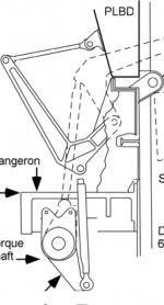
They're based on the attached schematic from Mechanical Systems Workbook.The "channel" for the monkey fur in the sides of the PLBDs, are the dimensions guesswork or is it referenced somewhere?
Attachments
- Joined
- Feb 4, 2008
- Messages
- 9,753
- Reaction score
- 1,024
- Points
- 203
Finally got some conclusions from sketching with the available data: a fwd bulkhead bending at Zo410 has an angle of about 2.9º, and if it starts at Zo420 the angle is ~3.3º. The PLBDs angle is about 3.3º which, if the seals are of constant width (I'd guess so), points to the Zo420 being the start of the bend.
Not super convinced, especially as I found a couple of structure CGI renderings in a Columbia crew survival report, which appear to show the bend at Zo410. But as I can't find a "smoking gun" either way, and as this has to be done and things have to fit, I'm going with Zo420. :shrug:
No idea what the PLBD seal "channel" dimensions are, so that will have to be done by eye.
Another thing that I want to do is correct the implementation of the PLBD "centerline": I don't know where it is exactly, so I won't change it, but I want to have the high point of the doors right at the center, so the fuselage is also centered, which means a new line of vertices will have to be added to one of the doors. Same goes for the NLG doors.
- Joined
- Feb 4, 2008
- Messages
- 9,753
- Reaction score
- 1,024
- Points
- 203
Based on my measurements, the channels measure 0.05736 m x 0.01275 m. This is based on the second PLB longeron schematic I posted earlier, knowing that they measure 0.2794 m x 0.254 m (11"x10" as seen from the front). So I just imported the schematic into AC3D, put it as an texture on a 0.2794 m x 0.254 m plane object, and then measured the channel dimensions.No idea what the PLBD seal "channel" dimensions are, so that will have to be done by eye.
Based on my measurements, the channels measure 0.05736 m x 0.01275 m. This is based on the second PLB longeron schematic I posted earlier, knowing that they measure 0.2794 m x 0.254 m (11"x10" as seen from the front). So I just imported the schematic into AC3D, put it as an texture on a 0.2794 m x 0.254 m plane object, and then measured the channel dimensions.
The problem is not on the side but at around the fwd bulkhead. I'm doing it such that it fits the existing side channels.
Any idea what the gap is between the PLBDs and the midbody sidewalls? I'm talking about the Zo420 hinge area, which has monkey fur exposed in the gap between the PLBDs and sidewall.
- Joined
- Feb 4, 2008
- Messages
- 9,753
- Reaction score
- 1,024
- Points
- 203
Judging by the schematics in JSC-11174, I have come up with 0.08 m (3.149606").Any idea what the gap is between the PLBDs and the midbody sidewalls? I'm talking about the Zo420 hinge area, which has monkey fur exposed in the gap between the PLBDs and sidewall.
Judging by the schematics in JSC-11174, I have come up with 0.08 m (3.149606").
As that is an estimate, I think I'll go with 3'' as it is a much rounder number.
---------- Post added at 07:25 PM ---------- Previous post was at 05:09 PM ----------
That can't be right... it's way too big. Looking at photos, it seems even 1'' would be too big. For now I'm going to leave both ends flush at Zo420.
- Joined
- Feb 4, 2008
- Messages
- 9,753
- Reaction score
- 1,024
- Points
- 203
I thought you were talking about the gap between the sidewalls and doors in the lateral axis when the doors are open.As that is an estimate, I think I'll go with 3'' as it is a much rounder number.
---------- Post added at 07:25 PM ---------- Previous post was at 05:09 PM ----------
That can't be right... it's way too big. Looking at photos, it seems even 1'' would be too big. For now I'm going to leave both ends flush at Zo420.
All the PLBD centerline latch stuff, is that positioned based on hard data or "guess work"? I' asking because in correcting the top end of the PLBDs (currently too high), all that stuff will need to come down a bit. Radiators as well.
- Joined
- Feb 4, 2008
- Messages
- 9,753
- Reaction score
- 1,024
- Points
- 203
The coordinates in the X-axis is based on actual data. Distance between the radiators and the door ribs are best estimates but it should be uniform all the way.All the PLBD centerline latch stuff, is that positioned based on hard data or "guess work"? I'm asking because in correcting the top end of the PLBDs (currently too high), all that stuff will need to come down a bit. Radiators as well.
Finished correcting the outline of the body of the PLBDs, only the interior stuff needs shifting in the centerline area, and the centerline shifted (by cutting at the correct location). BTW: is the current value correct?
One thing that could help position the top of the radiators is a payload max size diagram, as it probably has a payload-to-rad gap.
One thing that could help position the top of the radiators is a payload max size diagram, as it probably has a payload-to-rad gap.
- Status
- Not open for further replies.
Similar threads
- Replies
- 12
- Views
- 3K
- Replies
- 137
- Views
- 22K
- Replies
- 143
- Views
- 34K
- Replies
- 21
- Views
- 18K