My Homemade Propane+O2 Rocket Engine Design

Kaito

Orbiquiz Coordinator
Joined
Jul 24, 2008
Messages
857
Reaction score
0
Points
0
I guess I should start at the beginning...

I was looking up some rocketry videos on youtube, and came across the "fire in a jar" trick: put some ethyl alcohol in a 5 gallon water jug, vaporize (just shake it around), and drop a match in. It makes a giant woosh. I've seen this before, but watching it again made me think of wanting to try it. Eventually I tried it with a beer bottle...and it didn't make the woosh I was hoping for. But anyway, I was wondering if I could obtain any thrust from something like this. All rocket have their exhaust pointing down, so I would need to figure out a way to point it down, but have the contents not spill out...

I started talking with T.Neo about this, and after about 2 weeks of squabbling about injector designs, heat capacity, and structural integrity, I believe we have settled on a design capable of being built. The design I will be going off of is this, 95% accurate (very minor details need to be changed/were too hard to achieve in Wings3D), scale model of the engine. All that is not included is the throat and nozzle, which I consider to be trivial: http://imageshack.us/f/4/enginedetailed.jpg/

Color codes:

  • Red is combustion Chamber, imagined to be 2 mm thick aluminum piping

  • Blue and Green together represents the Injector, which propellant goes through will be determined later
  • The cyan piping around the chamber is piping that will carry water (in order to help with cooling). It is impossible to see in the picture, but they are in a spiral shape
  • The yellow jacket around the outside is an unspecified material that would serve two functions: Pressure resistance (in case the chamber wants to rip itself apart) and to also possibly aid in cooling, depending on it's material
The entire chamber is remarkably small: the chamber (just the tube, not including the top cap) is 10 cm long by 5 cm inner diameter. For another scale, the green protrusions are 2.54cm long, or exactly 1 inch.


Working out the Injector:
This had to be one of the hardest things to do. At first, I was thinking of just having two holes where I would inject my propellants, but T.Neo insisted on having them mix properly. We both made injector designs, and we didn't like each others. Eventually, T.Neo said "well, why not combine the best of both" (paraphrased), which is how I came up with this design. T.Neo did help with functionality adjustments. The spike at the very bottom of the blue tube is to help with deflecting the propellant down and out.


When I was modeling that picture, it occurred to me that there would be no effective way of injecting a propellant into the green tube. What I decided on doing is having 4 tubes project from it, and hand make an adapter (probably using rubber tubing and a fitting) to connect to the propellant tank. The blue tube would just be connected to a hose to the other tank. If anyone has any suggestions/constructive criticism to this design, please voice your opinions before I start constructing it.


Construction Methods/Structural Integrity
This was almost as painful for T.Neo and I as was building the Injector. I was not very worried about the structural Integrity of the chamber, but T.Neo was worried about it going up like a bomb. Here is MY planned construction method/materials:

  • The chamber WALLS would be made of aluminum, with the top cap probably steel
  • The blue, green, and cyan pipes would be made of copper
  • The yellow shell would either be made of PVC pipe (for nice pressure resistance) or a nice metal tube (not sure of the type of metal, all depends on what I can find for cheep)

  • The BLUE and GREEN tubes would be connected only at the top through welding/brazing. That would be it's only connection point
  • The GREEN and RED parts would be connected through threads, with a washer and nut on both sides to aid in support. I have the ability (mechanically, not skillfully yet) to cut both male and female threads, so hand making nuts and washes would not be a major concern to me.
  • The RED top cap and sides would be connected by having the top cap have flaps that fold over the sides, and then use bolts or screws to fasten them together. I also am thinking of using epoxy around the edges to make it air tight
  • the CYAN and RED parts would be connected at every accessible point by either epoxy, or welding, assuming they want to weld (I've heard that welding aluminum to other metals is quite hard)
  • The CYAN tubes would be connected to each other through vertical "beams" of welds
  • the YELLOW jacket wouldn't be fastened to the structure at all; it would either be mounted to the test stand, or just placed over the engine


I am not an expert welder/machinist, but I feel like this would be a good introduction to both of them while still having a cool project to do.


Performance Expectations
In order to make things simple, I decided to shoot for as much thrust as I could possibly get. Fuel efficiency does not mean much to me, as the fuels I'm using are relatively cheep, and fairly accessible. This being said, I am going to am for an absolutely outstanding and amazing thrust of:


1 Newton


If I can achieve even this minimal amount of thrust, I will be amazingly happy, and consider this engine a success. Anything over 1 Newton will be icing on the cake. I will always aim for more, but 1 is my goal.


For most of the controlled, scientific tests, I would have a burn time of about 5 seconds. This number is arbitrary, and I would happily change it if someone sees a concern. I feel this number would allow the chamber to feel the full stress, and thus any longer would mean minimal chance of failure.

Things not shown
There are some thing I did not include in this model, as I was mainly focusing on the engine. I did not show:

  • The propellant tanks
  • The throttling mechanism (a simple way to control both propellants at once, allowing for a fast shut off)
  • The igniter
  • The throat/nozzle
What I need help/assistance/ideas on
I feel like T.Neo and I have gotten to a good point in the design, but there are still some things that I am not clear on, or would like a second opinion or suggestion.

  • The throttle control. I'm mostly looking for a second opinion on this, but my idea is to have two valves along the hoses from the tanks to the injector. The throttle would just be a lever, connected via cables or some other mechanical connection, that would allow the turning of both valves simultaneously.
  • Connecting the top of the chamber to the sides. I need a second opinion/full design on this one. T.Neo is worried about the steel screws mounting the two together becoming overheated and losing their structural integrity. I do not think it will be a problem for the 5 second test, but I'm just not sure. I'm also slightly worried that the epoxy used to create an airtight seal wont be able to withstand the heat, but I'm not an expert on that.
  • The igniter. I need a full design on this one. I have salvaged a piezoelectric contraption from a lighter (ones used to light charcoal grills), and I was thinking of using it for an ignition source. My idea would be to connect it to a transformer to step up the voltage to create a nice spark (the current one is weak), and have a piston/motor contraption push the button in a regular and repeating fashion. I would then run wires up into the chamber, and cleverly place them so that they would ignite the propellants, and hopefully then the reaction is self-sustaining. I know I would lose my wires, but I cannot think of another way that would be cheep and simple. I do not wish to drill another hole in my chamber, but if I must, I will.
  • Test stand design. I just haven't thought about it much, so I am open to all ideas. My basic requirements are, however: Easy way to mount a water jug on top (in order to have water flow through the piping), cheep construction materials, and a place where I can place weights on it to prevent it from taking off (I know it won't, but I would feel safer)


Any suggestions would be appreciated. I plan to take pictures during the various construction phases and post them here, so you all can see how I'm doing. My first plan is to build either a prototype injector, or the actual injector, and test it with propane and compressed air (to simulate the O2), and use an open flame as an ignition source.


Be back here soon (hopefully) :hailprobe:


~Kaito
 
Last edited:

Gerdih

Member
Joined
Jan 8, 2010
Messages
775
Reaction score
7
Points
18
Location
Barcelona
If you have seen other threads about this you could see my threads about that. I have done a similar work with the help of a book. This book also explain how to do the test stand and mechanization advices. I can send you the pdf. Also it says thing about the igniter
 

Evil_Onyx

Well-known member
Joined
Jun 27, 2008
Messages
1,045
Reaction score
60
Points
63
Just a question about supplying the Propellants. How are you going to pressurize them or/and keep the pressure proportionally(ie mix ratio) the same all the way through the 5 sec burn?

---------- Post added at 00:46 ---------- Previous post was at 00:19 ----------

Have you considered using a spiral of metal welded to both the inner combustion chamber and the outer casing instead of the round pipe? It would both strengthen the combustion chamber and provide a better heat transfer to the coolant.
 

RisingFury

OBSP developer
Addon Developer
Joined
Aug 15, 2008
Messages
6,427
Reaction score
492
Points
173
Location
Among bits and Bytes...
First of all... please be careful. The last thing the OF community needs is Kaito with missing fingers. Firing the rocket engine isn't the only dangerous part. Sheets of metal are as sharp as knives so please wear heavy duty protective gloves.

Second, T.Neo is not the person to go to for rocket design, because he just made a mess of your design. Scrap the water cooling, it'll cause more harm than good. Metal can easily stand temperatures you'll be subjecting it to - especially with a 5 second burn. Here's a video of a home built RC pulse jet:


In fact, these things can glow red before they'll fail. Air cooling will suffice. You can estimate the temperature the engine will stay at by calculating how much energy is produced by the engine and assuming all of it goes into heating the engine, then balance that with radiative and convective cooling. And please don't ask T.Neo to do the calculations for you...

You don't need to worry about the engine blowing up either. The pulsejet in the video has much higher thrust, but more importantly, the tube at which it ejects the air is much longer. Your engine is much more open and the pressure can balance out more easily without putting a boatload of stress on it. I think the guy used stainless steel, but you can get more info on the xjet channel...

For protection when firing, get protective glass that stands up against projectiles.

Could you please explain better how you want your injector to work, because I don't understand a thing you're trying to say...
The injector is the most critical part. The pulsejet uses a pressure activated valve. When the mixture inside the engine detonates, the pressure closes the valve. The air ejects from the engine and that creates a partial vacuum, which sucks air in from the front, along with fuel. IIRC, the fuel is mixed with air by injecting it into the air continuously in front of the valve, so the air that gets sucked into the engine is already mixed.

The advantage of that design is simplicity, but the disadvantages are pulsed thrust (although at high frequency) and ware of the valve. This design will not work for you. For it to work, the engine needs to be relatively long, so the gas has time to work the valves. For you, no partial vacuum would be created for long enough for the air-fuel mix to be sucked in. The air would be sucked in from the back of the engine.


Keep in mind you'll need quite a lot of equipment for this to work. It's not something you find you the average basement.
For one, I'd scrap aluminium and copper and build the whole thing out of stainless steel. Aluminium doesn't do well at high temperatures and is very difficult to weld.
You'll need to know how to weld, cut and bend metal and you'll have to have equipment for it. It's not something you can do by hand. Using stainless steel only will make it a lot easier for you to work.
Epoxy also won't work well. It melts at high temperatures and is flammable, so lose it.


For throttling, I'd connect the valves to RC plane servos. That'll allow you to control the throttle remotely from a distance but with high precision.

Mounting: You don't have to worry about overheating. T.Neo: :facepalm:

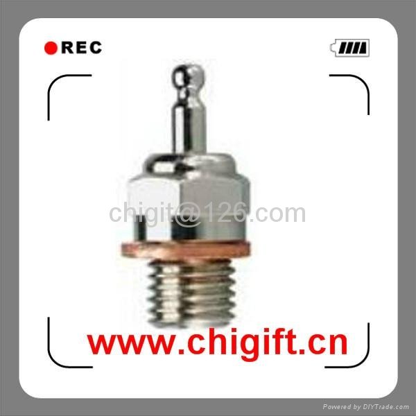
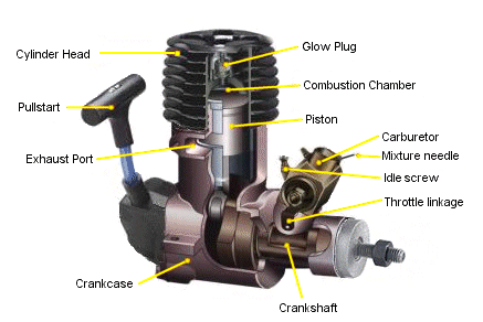
For the igniter I'd use RC plane glow plug:
glow_plug.jpg

Glow_Plug_for_RC_Nitro_Models.jpg

rc-nitro-car-engine-cutout.gif


These things survive at extreme pressures and temperatures.
Here's how it works in the RC nitro engine:
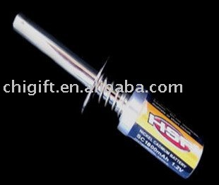
You first connect it to a glow plug heater. That's a 1.2 volt battery, usually NiH that passes current through the glow plug and makes it glow. You start the engine and then you can remove the glow plug heater, because the fuel mix keeps the glow plug hot.

For your engine, I'd keep the glow plug heater on all the time during the duration of the test.

Glow plug heater (same model I have):
80101_HSP_RECHARGABLE_NITRO_GLOW_PLUG_IGNITER.jpg


I'd use a hot glow plug (you can get everything from cold to hot to everything in between for different air temperatures and engine performance).


Hope this helps. Again, please explain how you think the injector will work.
 

T.Neo

SA 2010 Soccermaniac
Addon Developer
Joined
Jun 22, 2008
Messages
6,368
Reaction score
0
Points
0
I'm still not happy with Kaito's design;

- The cooling pipes don't make good contact with the chamber itself, limiting their effectiveness. I have suggested effectively submerging the entire chamber/nozzle in water, as a heatsink.

- The way the injector-end of the combustion chamber is fixed to the rest of the combustion chamber is undefined; Kaito has suggested welding an aluminium plate to the rest of the chamber, but my concern is the skill required for welding and the quality of the resultant weld.

- The way the parts that make up the injector attach to the rest of the chamber is also unclear; Kaito has suggested using threads, but some components do not posses enough material in this area for threads to exist.

- The morphology of the throat and/or nozzle is not defined; Kaito has suggested heating a piece of metal and forming it around a pre-made throat shape, but this sounds to me like a difficult and inexact process. In addition, this seperate piece would also have to be attached to the rest of the chamber somehow.

- The ability of this design (or any) to withstand mechanical (pressure) and thermal factors is not quantified. This worries me.

Keep in mind this isn't how I might build a small rocket engine, but a compromise (earlier, Kaito suggested essentially dumping the propellant into the chamber through two opposing pipes). Earlier I suggested a more conservative design, machined out of multiple thick pieces of metal and fitted together with screws, which Kaito didn't like.

How are you going to pressurize them

The propellants are either self pressurising (propane) or are a gas under pressure (GOX).

eep the pressure proportionally(ie mix ratio) the same all the way through the 5 sec burn?

That is a good question... :uhh:

because he just made a mess of your design

It is not my design.

And please don't ask T.Neo to do the calculations for you...

Could you perhaps be a bit more tactful? Some of Kaito's suggestions quite frankly make me want to tear my hair out in frustration, but you don't see me complaining. :tiphat:

Mounting: You don't have to worry about overheating. T.Neo:

Yes... well... fine... but, it all makes sense when you hear my philosophy!

When you know nothing, be overkill and underdeliver. :p
 
Last edited:

MaverickSawyer

Acolyte of the Probe
Joined
Apr 11, 2011
Messages
3,919
Reaction score
5
Points
61
Location
Wichita
:hmm: Good thing you're not cutting metal yet!
Problems:
1. Welding aluminum to itself, let alone to other materials, is a bitch and a half, according to a friend who's a welder. The combustion chamber should be a single material, not a composite. The composite design is a :dynamite:... Steel should suffice. Weld the chamber together. And you need to figure out how much thicker it needs to be, because that's nowhere neat thick enough for the pressure. Again, :dynamite:

2. The injector is going to be... interesting. Watch out for combustion instability, which can lead to RUDs: Rapid Unintended Disassembly. Another :dynamite: problem, and one that may cause considerable grief.

3. Cooling: You're not going to get the needed cooling with that design. You'll get minimal cooling at the contact points, and NONE at the gaps. Once again, :dynamite:. Two options: Either a heatsink combustion chamber, which is ideal for testing the injector for short burns, or a jacketed chamber, which would be for flight, but is an extremely challenging design.

4. Propellant supply: Do not feed the O2 gas through a system with combustible materials in its design! You should have no trouble brazing or even welding the tubes on. The challenge will be machining them to fit.

5. Test Stand: Point the engine straight up, so that it would be forced down. This allows you access to the engine with ease, perform inspections, extinguish fires, etc.
Given the DIY nature of this project, do it as far from buildings as possible, and have a blast abatement rig, i.e. sandbags, dumpster, etc to catch the blast. Observe with mirrors or some other remote view system. Parts are replaceable: you are not! :)

6. Throttle: You'll want to have the mixture already set before you fire. Failure to do so can yield another :dynamite:. Use a set of linked ball valves to control flow. I don't know if you can safely modify electric sprinkler valves to run compressed O2...

7. Ignition: Ford ignition coil and a sparkplug, or a sparkler firework. Glow plug should work too. :)

8. Epoxy: For the love of :probe:, DON'T! :facepalm:

Overall, not bad. I would do some cold flow tests first, with compressed nitrogen in place of both propellants, and check for a good mixing pattern, whatever that is. :shrug:
As for the nozzle and throat: Pffft. forget them for now. just get the damned thing to run safely and stably, then worry about the throat and nozzle.
Good luck, and hope this helps!
 

Veterok

New member
Joined
Oct 25, 2011
Messages
65
Reaction score
0
Points
0
Just a question about supplying the Propellants. How are you going to pressurize them or/and keep the pressure proportionally(ie mix ratio) the same all the way through the 5 sec burn?

---------- Post added at 00:46 ---------- Previous post was at 00:19 ----------

Have you considered using a spiral of metal welded to both the inner combustion chamber and the outer casing instead of the round pipe? It would both strengthen the combustion chamber and provide a better heat transfer to the coolant.

I might not be understanding your suggestion correctly, but wouldn't that be next to impossible to actually put together? Once you weld the spiral onto the combustion chamber you don't have enough room to weld it to the outer wall from the inside.

I would suggest forgetting piping the water around the chamber, just use two concentric tubes and run water between their walls. It's a stationary test engine right? Just hook it up to the hose and leave the water running while you fire it.
 

agentgonzo

Grounded since '09
Addon Developer
Joined
Feb 8, 2008
Messages
1,649
Reaction score
4
Points
38
Location
Hampshire, UK
Website
orbiter.quorg.org
(I've heard that welding aluminum to other metals is quite hard)
That's an understatement. My knowledge of it goes back to GCSEs, but basically you need a special welder that uses a different metal for the flux. And even then it's extremely hard. No offence, but if you're not a skilled welder I very much doubt that you would be able to do it - I certainly wouldn't.
 

Evil_Onyx

Well-known member
Joined
Jun 27, 2008
Messages
1,045
Reaction score
60
Points
63
I might not be understanding your suggestion correctly, but wouldn't that be next to impossible to actually put together? Once you weld the spiral onto the combustion chamber you don't have enough room to weld it to the outer wall from the inside.

That did occur to me this morning... the solution is to use a strip of the metal and weld each side to the spiral. But as has been suggested for the small size of the chamber its more hassle to use liquid cooling anyway.
 

N_Molson

Addon Developer
Addon Developer
Donator
Joined
Mar 5, 2010
Messages
9,290
Reaction score
3,258
Points
203
Location
Toulouse
(I've heard that welding aluminum to other metals is quite hard)

I confirm, from my little experience with sailboats hulls, aluminium requires industrial hardware. I knew a retired professional welder that built a 11-meters hull with steel, but aluminium is another thing.
 

RGClark

Mathematician
Joined
Jan 27, 2010
Messages
1,635
Reaction score
1
Points
36
Location
Philadelphia
Website
exoscientist.blogspot.com
2. The injector is going to be... interesting. Watch out for combustion instability, which can lead to RUDs: Rapid Unintended Disassembly. Another :dynamite: problem, and one that may cause considerable grief.

Meaning explosion. No use using euphemisms here.

Bob Clark

---------- Post added at 03:04 PM ---------- Previous post was at 03:01 PM ----------

If you have seen other threads about this you could see my threads about that. I have done a similar work with the help of a book. This book also explain how to do the test stand and mechanization advices. I can send you the pdf. Also it says thing about the igniter

Perhaps you mean this book:

HOW to DESIGN, BUILD and TEST SMALL LIQUID-FUEL ROCKET ENGINES.
ROCKETLAB / CHINA LAKE, CALIF.
http://www.risacher.org/rocket/


Bob Clark

---------- Post added at 03:56 PM ---------- Previous post was at 03:04 PM ----------

First of all... please be careful. The last thing the OF community needs is Kaito with missing fingers. Firing the rocket engine isn't the only dangerous part. Sheets of metal are as sharp as knives so please wear heavy duty protective gloves.

Second, T.Neo is not the person to go to for rocket design, because he just made a mess of your design. Scrap the water cooling, it'll cause more harm than good. Metal can easily stand temperatures you'll be subjecting it to - especially with a 5 second burn. Here's a video of a home built RC pulse jet:

Pulsejet powered World Models TameCat RC plane, maiden flight - YouTube

I'd advise using a cooling system of some kind. If you're going to use O2 gas or LOX then you're going to get hotter burning temperatures. Pure oxygen always results in hotter flame temperatures than ambient air, as the nitrogen in air which is not involved in the combustion serves to cool the flame. It's why rockets typically burn hotter than jet engines.


Bob Clark
 

MaverickSawyer

Acolyte of the Probe
Joined
Apr 11, 2011
Messages
3,919
Reaction score
5
Points
61
Location
Wichita
The thermal pulse from a 5 second burn should not be a problem. That's also a reasonable amount of time to test for stable combustion. If Kaito goes for longer burns, then he will need cooling, as well as better materials.
 

Urwumpe

Not funny anymore
Addon Developer
Donator
Joined
Feb 6, 2008
Messages
37,632
Reaction score
2,350
Points
203
Location
Wolfsburg
Preferred Pronouns
Sire
The injector design isn't that good, you lack the atomization of the fuel being injected. Even with a longer combustion chamber (that costs mass), it will be rather ineffective and below ideal temperatures. A lot of combustion might even take place outside the chamber.

Because of the small size that you aim for, I would suggest making the front end of the chamber an inverted cone (tip goes to the front), and drill four to eight holes normal into the surface of the cone, so they focus at the base of the cone. Interleave oxygen and fuel injector holes.

Remember to drill the holes in a special way, they have to be convergent at the end, so the injected gases expand divergent.

Drill a hole with winding into the tip of the cone, for accepting the igniter, maybe put two injector nozzles there to bring more propellant close to the igniter.

Drop the liquid cooling stuff. It costs a lot of mass and is not needed. If at all, put fins around the engine to increase the radiator surface. If you worry about the chamber walls, use film cooling or ablative cooling for such short burns.

And be careful. Oxygen is very nasty especially if it imparts on hot metal parts.

Maybe you should consider using hydrogen peroxide as oxidizer and gasoline as fuel. Both has much higher density and is relatively easy to obtain in the quantities that you need for testing. And peroxide is much easier to handle if you follow the safety rules by the letter, than oxygen, which requires an understanding of the nature of oxygen.
 

T.Neo

SA 2010 Soccermaniac
Addon Developer
Joined
Jun 22, 2008
Messages
6,368
Reaction score
0
Points
0
The injector design isn't that good, you lack the atomization of the fuel being injected. Even with a longer combustion chamber (that costs mass), it will be rather ineffective and below ideal temperatures. A lot of combustion might even take place outside the chamber.

Because of the small size that you aim for, I would suggest making the front end of the chamber an inverted cone (tip goes to the front), and drill four to eight holes normal into the surface of the cone, so they focus at the base of the cone. Interleave oxygen and fuel injector holes.

Remember to drill the holes in a special way, they have to be convergent at the end, so the injected gases expand divergent.

Drill a hole with winding into the tip of the cone, for accepting the igniter, maybe put two injector nozzles there to bring more propellant close to the igniter.

My original suggestion was to inject the propellant through two narrow circular openings at the edge and center of the chamber (with a pintle in the center, as in a hosepipe attachment), as in this crude cutaway view:

attachment.php


Could such an arrangement be effective at all?

If you worry about the chamber walls, use film cooling or ablative cooling for such short burns.

How many burns could an ablative coating or liner be used for before needing to be replaced? Kaito doesn't like the idea of an ablative that has to be replaced for each firing.

Maybe you should consider using hydrogen peroxide as oxidizer and gasoline as fuel.

What about nitrous oxide as an oxidiser?
 
Last edited:

MaverickSawyer

Acolyte of the Probe
Joined
Apr 11, 2011
Messages
3,919
Reaction score
5
Points
61
Location
Wichita
H2O2 and gasoline should be fairly close to hypergolic.
The pintle design is interesting. Probably the most stable burn, but also fairly complex... :hmm: unless he can drill inside the combustion chamber, the injector's going to have to be a 2 piece.
 

Urwumpe

Not funny anymore
Addon Developer
Donator
Joined
Feb 6, 2008
Messages
37,632
Reaction score
2,350
Points
203
Location
Wolfsburg
Preferred Pronouns
Sire
My original suggestion was to inject the propellant through small circular openings at the edge and center of the chamber (with a pintle in the center, as in a hosepipe attachment), as in this crude cutaway view:

Would work if you create a cyclon flow inside the chamber, there are some designs that work like that. Also creates a good film for cooling the engine walls then, but the fuel/oxidizer mixture is still not close to optimal, but you could afford it.

But I think, even for a 60 second burn, you will not get close to the point where cooling the engine by airflow or radiative will fail. Air cooling should work at least, if you want to improve it, use inlets for directing more air past the engine cooler.

How many burns could an ablative coating or liner be used for before needing to be replaced? Kaito doesn't like the idea of an ablative that has to be replaced for each firing.

Ok, then it is not suitable, since you practically need to renew the ablative coating after every firing.

What about nitrous oxide as an oxidiser?

Much better choice, but you have to remember that it is self-pressurizing at a fairly high steam pressure.
 

kuddel

Donator
Donator
Joined
Apr 1, 2008
Messages
2,064
Reaction score
508
Points
113
Hello,

I just want to make sure that you should not 'try' when working with O2!
Please do yourself a favor and ask someone that really has knowledge about handling O2.
And I don't mean "someone who has build something and posted it on youtube", I mean professionals!
As urwumpe -or was it someone else- already mentioned, O2 is a very nasty thing if not handled properly.

For example you should NEVER use regular valves for controlling O2-Flow, because most valves include grease to make them air- or water-tight.
Fat (grease, oil) and O2 don't work well together!

For a slightly insight of O2-Handling please read (at least) this:

Safety principles of high pressure oxygen systems

Be careful, be safe

Kuddel
 

Kaito

Orbiquiz Coordinator
Joined
Jul 24, 2008
Messages
857
Reaction score
0
Points
0
Wow, thank you for all the advice! I have a couple things I'd like to say:

1) I guess I'll have to entirely redesign the engine now, due to the overwhelming support for air cooling
2) I do not intend for this to be airborne. This engine will remain firmly on the ground, so mass that is not directly on the engine does not matter to me.
3) The propane and O2 I would be using would be in gaseous form by the time they hit the injector, so I was not concerned about atomization.
4) I had not thought about using gasoline as a fuel. I've been thinking about that, and I think I might want to switch to that. It does seem to have a much higher energy density than propane.
5) Obtaining reasonable concentrations of hydrogen peroxide to be used as an oxidizer would be relatively hard, I fear. Plus, about the oxygen as an oxidizer...I am not a complete moron when it comes to oxygen: I know that it can be dangerous if used wrong, so I would be careful with it

I'm just brain storming here, and I'll draw up a model sometime in the coming days, but I was thinking having the gasoline be in a container, and have Nitrogen gas (It's stored at 153 bar in the tank, well above any chamber pressure I imagine I'd reach) forced into the gasoline to force it through an injector. This way, there is no chance of the gasoline burning back into my container. I know the gasoline would not come out of the injector at 153 bar, but I know my chamber pressure wouldn't that ridiculously high.

As far as atomization of the gasoline goes, I'm not sure how to do that. My thought would be to force the gasoline, under the pressure of nitrogen, through some small holes that would almost break it up into small droplets that evaporate quickly. I could also place these strategically such that they intersect with the path of the oxidizer, further breaking it up.

Like I said, I'll attempt to post a concept model in the coming days.

Thank you again,
~Kaito

EDIT:
I had an idea for a simple ignition source. There are these slow burning firework lighters (Known to me as 'punks'). You light them with a lighter, and they remain fairly dormant until you blow on them. Then they glow red hot, and can be used to light firework fuses. My idea is to buy a pack of these (I can get a pack of 20 for incredibly cheep), light it, and place it in the engine minutes before the test. Then, say, 3 seconds before ignition, I would open up the oxidizer valves, which would blow oxidizer over it, causing it to glow RED hot (If it's hot enough to burn using just air, I imagine it would glow MUCH hotter when in the presence of an actual oxidizer). Then, I would introduce the fuel. I imagine that this would ignite the engine fairly reliably, as it is almost as good as having an open flame right in the engine. I know it would need to be replaced after each test, but it's a simple task. Any thoughts on this?

---------- Post added 12-01-11 at 09:39 AM ---------- Previous post was 11-30-11 at 11:52 PM ----------

Picture time!

For the purposes of this design, I assuming I am using gasoline and Gaseous Oxygen (GOX)

View 1, showing relative positions of all the parts: Red is the chamber, Blue is the Gasoline, Green is the GOX, and the cyan part is designed to turn the gasoline into more of a mist. It is cut into quarters so that I could get a better picture of the Cyan part.

View 2, showing how the cyan part works. The spike in the center is meant to help deflect the gasoline downward. As you can (hopefully) see, there are gaps between the Cyan and blue parts. This drawing is not to scale, but the idea is to make those gaps big enough to let gasoline through, but only in small amounts at a time, so it either comes out as a mist right away, or rapidly evaporates. The green tubes are placed so that the gasoline has to travel right into the path of it, further helping the atomization process.

Please let me know if this design would work for gasoline. If it works, it would be an incredibly simple injector design.

As far as my ignition idea goes, I was thinking of using one of these (the stick coming from the right hand side) to light it. I would break it up into three or four parts, and stick them inside the chamber via a wire stand. Before I stick them in, I would light them, so that they are smouldering. When I'm ready to fire, I would turn on the O2 FIRST, so that the punks burn, and burn quite hot. I would then introduce the gasoline (The time difference between opening the two valves would be less than a second). I know I would lose the punks, and possibly the stand, depending on the test duration.

For pressure feeding the Gasoline, I would use a homemade steel container hooked up to a Nitrogen tank, and use that to feed the propellant into the chamber.

Thoughts/Feedback is always welcome

~Kaito
 
Last edited:

Urwumpe

Not funny anymore
Addon Developer
Donator
Joined
Feb 6, 2008
Messages
37,632
Reaction score
2,350
Points
203
Location
Wolfsburg
Preferred Pronouns
Sire
I sense trouble in that design, sorry.

Also, you should remember that hot oxygen already reacts with your fingerprints. As well as many metals that are commonly available. It is very dangerous if you are not having professional tools at hand. You would need not just a lathe, but also something to really clean the parts of any contamination.

It is not really something for the beginner. You better learn combusting oxygen first, in designs that can burn off if you do something wrong. The learning curve for oxygen is way steeper than for Orbiter.

Nitrogen oxide (laughing gas) is also available in the quantities that you need, and also an excellent "fool-proof" (with some disclaimers" oxidizer.
 

Kaito

Orbiquiz Coordinator
Joined
Jul 24, 2008
Messages
857
Reaction score
0
Points
0
I sense trouble in that design, sorry.
Can you state which elements wont work? Are you talking about my idea of vaporizing the gasoline?

Also, you should remember that hot oxygen already reacts with your fingerprints. As well as many metals that are commonly available. It is very dangerous if you are not having professional tools at hand. You would need not just a lathe, but also something to really clean the parts of any contamination.
My hand will be no where near the chamber while any propellant is flowing from the tank. And by that I mean, when we are not behind the protective barrier, the TANK VALVE will be turned off. I also have access to solvents and various chemicals that are designed to clean metal. They are not specifically designed to clean metal for contact with high pressure oxygen, but they are designed to clean metal.

It is not really something for the beginner. You better learn combusting oxygen first, in designs that can burn off if you do something wrong. The learning curve for oxygen is way steeper than for Orbiter.
I understand the implications of working with Oxygen. I am appreciative that you guys care about my safety, and I am trying to take every safety advice into account with my design.

Nitrogen oxide (laughing gas) is also available in the quantities that you need, and also an excellent "fool-proof" (with some disclaimers" oxidizer.
In my (admittedly small) amount of research, I have found that Nitrous Oxide tanks are quite expensive, at least where I was looking. I'm sure I could find them cheaper, however I already have access to an Oxygen tank at home.

Any other ideas/concerned with using Oxygen, I'd be happy to hear. but please do not tell me just to "not use it" because it is dangerous. I know it's dangerous

~Kaito (who will NOT be missing a finger, or toe, or hand, or arm, or head anytime soon...or body)
 
Top