Question What is an electrical bus exactly?

Linguofreak

Well-known member
Joined
May 10, 2008
Messages
5,038
Reaction score
1,275
Points
188
Location
Dallas, TX
I'm under the impression that in a conductor, it's the amps generating the heat, not the volts. So if too many amps are drawn, the voltage drops to accommodate more amps, hence you get more heat at the same power.
I might have a severe misconception here, but I thought this was the reason why long-range power transfers are conducted at as high a voltage as possible.

The amps generate the heat, but you can't dissipate 200 Watts of heat from a circuit that only gets 100 watts from its power supply (at least not in the long run. If you have capacitors or inductors storing energy within the circuit, you might momentarily get out more than you take in, but in the long run energy must be conserved ). Once the current is high enough to dissipate the full wattage of the power supply through resistances in the circuit, the current stops growing and the voltage stops falling.
 

jedidia

shoemaker without legs
Addon Developer
Joined
Mar 19, 2008
Messages
10,891
Reaction score
2,141
Points
203
Location
between the planets
By dropping the voltage, the current also drops which reduces the load.

Not quite sure I follow. When the voltage drops, eventually consumers will drop of the net, so current will drop too.
But before that happens, doesn't the current increase?
 

C3PO

Addon Developer
Addon Developer
Donator
Joined
Feb 11, 2008
Messages
2,605
Reaction score
17
Points
53
Not quite sure I follow. When the voltage drops, eventually consumers will drop of the net, so current will drop too.
But before that happens, doesn't the current increase?

Only if the "consumer" has a regulated power output. It's much more likely that the consumer has a specific impedance (Z), so the power consumption will fall with the falling voltage.
 

jedidia

shoemaker without legs
Addon Developer
Joined
Mar 19, 2008
Messages
10,891
Reaction score
2,141
Points
203
Location
between the planets
Right. Almost there. There's one last thing that confuses me, and I can't really seem to find an answer for it without pulling out my wallet.

The problem concerns parallel circuits, which buses allegedly are.
I can work with parallel circuits. The math is trivial, the concepts simple. But all the examples are with only one power source. What happens if you connect two power sources to a parallel circuit (with same voltage, the other just gets weird).

The confusion I'm having is because current varies in parallel circuits. So intuition (which is known to have been wrong many times before) would suggest that it actually matters where in the circuit you plug in the second power source. Consider the below incomplete and very badly drawn diagram:

attachment.php


PS1 and 2 are of course power supplies, and we have two resistors demanding 3 and 2 amps respectively (I know you'd usually give the resistance in Ohm and declare the voltage, but I'm simplifyig for concepts sake here.

Let's for a moment assume that PS2 doesn't exist. Then it is a very imple case: There's 5 amps drawn from PS1, and if I measure the current between the first and the second resistor, I get 2 amps. Simple enough.

But I don't know what happens if I plug PS2 into that circuit. As I said, intuitively I would expect 3 amps being drawn from PS1 and 2 amps from PS2, but the problem is that then I'm effectively getting two different circuits. If I now measure the current between PS1 and the first resistor, I'd only get 3 amps instead of 5. So plugging in PS2 completely changes the characteristics of the whole circuit, which makes me very hesitant. It feels odd. I suspect there's another misconception in here.
 

Attachments

  • parallel.jpg
    parallel.jpg
    11.7 KB · Views: 68

ADSWNJ

Scientist
Addon Developer
Joined
Aug 5, 2011
Messages
1,667
Reaction score
3
Points
38
PS1 and PS2 have ~no resistance between their respective poles, so either PS1+ is identical to PS2+ and PS1- is identical to PS2- (in which case PS1 and PS2 are essentially the same PS), or you will have a huge current between the two batteries, equal to the delta-Voltage divided by the minimal wire-only resistance.
 

C3PO

Addon Developer
Addon Developer
Donator
Joined
Feb 11, 2008
Messages
2,605
Reaction score
17
Points
53
I think you are confusing electrical diagrams, wiring diagrams and single-line diagrams. Buses are generally drawn in single-line, but that doesn't say anything about the wiring. It depicts an overview of the connected parts. A bus isn't parallel unless you tie two buses together. (like during switching without cutting power, or if demand exceeds available power of a single bus)

However power supplies and consumers are connected to the bus in parallel. A single bus is not considered parallel, even if the actual wiring is.

I'm guessing the most of the confusion stems from the single-line diagrams. It can be 1-wire + ground, 2-wire, 3-wire (3 phase) or 4-wire (3 phase + Neutral)

In your example the two horizontal lines (wires) could be considered a bus. If I had to draw an electrical diagram of that system it would look like this:
Parallel.jpg
The horizontal lines could be considered as "immaculate" wires with no losses.
 

HarvesteR

Member
Joined
Apr 22, 2008
Messages
386
Reaction score
15
Points
18
I think in that case you're actually drawing 5 amps from both sources. When hooked up in parallel, they effectively share the conditions of the entire system, regardless of where they're placed.

The result in this case of adding a second PS is that the load is reduced for any one of them. The length of the wiring between each component (in this scale) shouldn't really matter. They might be placed side by side or on opposite ends of the bus, they'll be doing the same thing.

For the load on each source, I might be wrong, but I would think each PS would contribute half of the total draw. Adding a third PS would make each contribute 1/3rd, and so on.

Cheers
 

C3PO

Addon Developer
Addon Developer
Donator
Joined
Feb 11, 2008
Messages
2,605
Reaction score
17
Points
53
PS1 and PS2 have ~no resistance between their respective poles, so either PS1+ is identical to PS2+ and PS1- is identical to PS2- (in which case PS1 and PS2 are essentially the same PS), or you will have a huge current between the two batteries, equal to the delta-Voltage divided by the minimal wire-only resistance.

In reality there is no power supply with no resistance. When calculating current a battery cell is represented by a constant voltage and an "inner resistor" to calculate the voltage of the battery terminals. As the cell is discharged the inner resistor increases, lowering the voltage on the terminals.

---------- Post added at 07:42 PM ---------- Previous post was at 07:41 PM ----------

... but I would think each PS would contribute half of the total draw. Adding a third PS would make each contribute 1/3rd, and so on.

Correct.
 

ADSWNJ

Scientist
Addon Developer
Joined
Aug 5, 2011
Messages
1,667
Reaction score
3
Points
38
In reality there is no power supply with no resistance. When calculating current a battery cell is represented by a constant voltage and an "inner resistor" to calculate the voltage of the battery terminals. As the cell is discharged the inner resistor increases, lowering the voltage on the terminals.

I wasn't talking about the battery resistance, but rather the wires. Consider a 12V car battery wired to a 1.5V Type D battery with + to + and - to -. I assume the 12V battery just discharges down to 1.5V, and the wires get hot.
 
Last edited:

kuddel

Donator
Donator
Joined
Apr 1, 2008
Messages
2,064
Reaction score
508
Points
113
All this is covered by Kirchhoff's laws (https://en.wikipedia.org/wiki/Kirchhoff's_circuit_laws).
"Point rules" and "loop rules" are exactly what you need to apply here.
Once you have understand how to deal with the "signs" (current flow direction) it's basically just addition and subtraction of currents rsp. voltages.

The wikipedia article might however not be the best to "teach" you how to do that, but once you know the name google is very helpful :)
 

jedidia

shoemaker without legs
Addon Developer
Joined
Mar 19, 2008
Messages
10,891
Reaction score
2,141
Points
203
Location
between the planets
In your example the two horizontal lines (wires) could be considered a bus. If I had to draw an electrical diagram of that system it would look like this:

Thanks, I understand your diagram, but I'm not quite sure of its meaning. Do you mean to say that parallel powersupplies have to be wired this way or it won't work, or do you mean that it is merely a matter of representation, i.e. that the physical order of the supplies/resistors in the circuit does not actually matter as long as they're wired in parallel?

"Point rules" and "loop rules" are exactly what you need to apply here.

Thanks, I'll go look that up then.
 

C3PO

Addon Developer
Addon Developer
Donator
Joined
Feb 11, 2008
Messages
2,605
Reaction score
17
Points
53
I wasn't talking about the battery resistance, but rather the wires. Consider a 12V car battery wired to a 1.5V Type D battery with + to + and - to -. I assume the 12V battery just discharges down to 1.5V, and the wires get hot.

That would make the D cell explode. Lead Car batteries are designed to deliver relatively high current. If you want to tie power supplies you need then to have identical nominal voltage, and a similar reaction curve. You certainly wouldn't design a bus with that option.
 

kuddel

Donator
Donator
Joined
Apr 1, 2008
Messages
2,064
Reaction score
508
Points
113
Right. Almost there. There's one last thing that confuses me, and I can't really seem to find an answer for it without pulling out my wallet.

The problem concerns parallel circuits, which buses allegedly are.
I can work with parallel circuits. The math is trivial, the concepts simple. But all the examples are with only one power source. What happens if you connect two power sources to a parallel circuit (with same voltage, the other just gets weird).

The confusion I'm having is because current varies in parallel circuits. So intuition (which is known to have been wrong many times before) would suggest that it actually matters where in the circuit you plug in the second power source. Consider the below incomplete and very badly drawn diagram:

attachment.php


PS1 and 2 are of course power supplies, and we have two resistors demanding 3 and 2 amps respectively (I know you'd usually give the resistance in Ohm and declare the voltage, but I'm simplifyig for concepts sake here.

Let's for a moment assume that PS2 doesn't exist. Then it is a very imple case: There's 5 amps drawn from PS1, and if I measure the current between the first and the second resistor, I get 2 amps. Simple enough.

But I don't know what happens if I plug PS2 into that circuit. As I said, intuitively I would expect 3 amps being drawn from PS1 and 2 amps from PS2, but the problem is that then I'm effectively getting two different circuits. If I now measure the current between PS1 and the first resistor, I'd only get 3 amps instead of 5. So plugging in PS2 completely changes the characteristics of the whole circuit, which makes me very hesitant. It feels odd. I suspect there's another misconception in here.

Hi again,

let's start over and try to apply Kirchhoff's Laws:

1. Let's rearrange the circuit, so that we can see more clearly where nodes and where loops are (see attachment)
attachment.php

I(2) is 2 Amps, I(3) is 3 Amps, therefor the current that flows out of Pt1 (and into Pt2) is 5 Amps!
That however implies, that 5 Amps have to flow into Pt1 (and out of Pt2)!
The only unknown that remains is: What kind of power supplies we have.
If both are equal (in terms of voltage and internal resistance), then they share the load equally (each one 2.5 A).
If their internal resistances have a ratio of 2:3 however, ...guess what ;)

/Kuddel
 

Attachments

  • redrawn.png
    redrawn.png
    31.4 KB · Views: 67

C3PO

Addon Developer
Addon Developer
Donator
Joined
Feb 11, 2008
Messages
2,605
Reaction score
17
Points
53
Thanks, I understand your diagram, but I'm not quite sure of its meaning. Do you mean to say that parallel powersupplies have to be wired this way or it won't work, or do you mean that it is merely a matter of representation, i.e. that the physical order of the supplies/resistors in the circuit does not actually matter as long as they're wired in parallel?

In an electrical diagram the order is irrelevant. In a wiring diagram the actual position can be relevant depending on the type of equipment/cables used.

I'm sorry if I'm adding to the confusion, but I've worked so long with stuff like this that it's intuitive to me, and I find it hard to explain in detail. And not having English as my native language doesn't help. :lol:
 

ADSWNJ

Scientist
Addon Developer
Joined
Aug 5, 2011
Messages
1,667
Reaction score
3
Points
38
That would make the D cell explode. Lead Car batteries are designed to deliver relatively high current. If you want to tie power supplies you need then to have identical nominal voltage, and a similar reaction curve. You certainly wouldn't design a bus with that option.

Yup - that's the point I was trying to get to with the PS1 and PS2... if they are not at the same voltage on each terminal, then bad things will happen in Jedidia's circuit.
 

jedidia

shoemaker without legs
Addon Developer
Joined
Mar 19, 2008
Messages
10,891
Reaction score
2,141
Points
203
Location
between the planets
Let's rearrange the circuit, so that we can see more clearly where nodes and where loops are (see attachment)
Click this bar to view the full image.

Thanks, that makes things somewhat clearer. So the powersupplies have to connect to a common point in order to really work in parallel, not just be somewhere in the circuit wired in parallel. That's essentially what I was wondering.

I've tried playing around with circuit simulators in the last 2 hours, but I haven't found a single one that does parallel power sources. :(

I've worked so long with stuff like this that it's intuitive to me

Don't worry, I know how that feels :lol:

In any case, everyone here has been a big help, thanks a lot! With this last piece of information I think I can finally start to design some data structures for my power distribution.
 

kuddel

Donator
Donator
Joined
Apr 1, 2008
Messages
2,064
Reaction score
508
Points
113
Back to the original issue ("power bus"):

First let's recall how the power supply is able to deliver a specific amount of current:
I take the liberty and discuss this on examples with batteries.

Every battery has two properties:
1. The open-circuit voltage Voc
2. The internal resistance (or ESR for Equivelent Series Resistance)

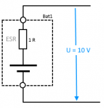
When measuring the voltage of the battery (open circuit) the voltage at the connectors equals the Voc
because there is no current flowing and therefore there is no voltage drop over the ESR

attachment.php


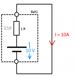
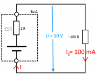
This battery for example has a Voc of 10V and an ESR of 1 Ohm.
If we short circuit this battery, 10A will flow [1].
attachment.php

This is the maximum current this power-supply can deliver.


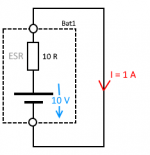
The second battery for example has also a Voc of 10V, but an ESR of 10 Ohms.
If we measure the voltage (open-circuit) it is also 10V - again, because no current is flowing and
therefore there is no voltage drop over the ESR).
If we short circuit this battery, 1A will flow. This is the maximum current this power supply can deliver.

attachment.php


Now lets add a simple drain (a 100 Ohms Resistor) in our simple circuit:
If we measure the current, we would expect it to be 100mA (Remember Ohms law: I=U/R => I = 10V / 100 Ohm)
Actually we would measure a little bit less, because of the internal resistance of the battery ( I = 10 V / (100 + 1) Ohm )
But that is not really important here...

attachment.php


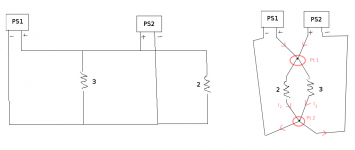
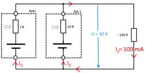
Now let's add our second battery to the circuit:

attachment.php


Now the current through the resistor will still be 100 mA (for our calculations here we assume this).
That 100 mA flows into node 1, but from here the current will divide up into the different currents through
our two batteries:
Through the first battery (ESR 1 Ohm) a current of 99 mA will flow and
through the second battery (ESR 10 Ohms) a current of 1 mA will flow.

So the first battery will have to deliver a little bit less current (compared with our "one-battery" example before) because the second battery will now contribute one tenth of
the total current (that flows through the 100 Ohms resistor).

...Hope this helps.

P.S.: Any errors here are definitely mine :lol:
(if anyone find some, please tell me so I can fix 'em)
---
[1] The only element limiting the current is the ESR => I = U/R => I = 10V/1Ohm => 10 A
 

Attachments

  • Open-circuit.png
    Open-circuit.png
    4.3 KB · Views: 67
  • Short-circuit.png
    Short-circuit.png
    5.2 KB · Views: 67
  • bat-2.png
    bat-2.png
    5.2 KB · Views: 68
  • first-circuit.png
    first-circuit.png
    7.5 KB · Views: 68
  • second-circuit.png
    second-circuit.png
    11.2 KB · Views: 67
Last edited:

kuddel

Donator
Donator
Joined
Apr 1, 2008
Messages
2,064
Reaction score
508
Points
113
And by the way, a tutorial by Dave on Kirchhoff's Laws:

(don't miss the 2nd part!)
 
Last edited:

jedidia

shoemaker without legs
Addon Developer
Joined
Mar 19, 2008
Messages
10,891
Reaction score
2,141
Points
203
Location
between the planets
Thanks a lot, I'm getting there. One question that just poped up that I'm not quite sure about: Suppose in my above diagram I simplified so heavily that I abstracted an entire circuit as a power source. Then the internal resistance of that "power source" would be the overall resistance of the circuit, correct?
 

Dantassii

HUMONGOUS IMS shipbuilder
Joined
Jul 14, 2012
Messages
508
Reaction score
20
Points
33
Jedidia? They are going to make an Electrical Engineer out of you yet. :)

Dantassii
Why yes, I am a Rocket Scientist
BS, MS, Ph.D. Aerospace Engineering (Well almost)
 
Top