You are using an out of date browser. It may not display this or other websites correctly.
You should upgrade or use an alternative browser.
You should upgrade or use an alternative browser.
Project SSU HI RES Textures
- Thread starter Wolf
- Start date
- Joined
- Feb 4, 2008
- Messages
- 9,761
- Reaction score
- 1,029
- Points
- 203
Oops! Sorry about that. I have edited and fixed the links.The pics look the same.
Found another issue with the hi-res textures: https://www.dropbox.com/s/yhgbr38rp0vezxf/ET_attach_not_aligned.jpg?dl=0
As you can see, the "salad bowl" of the -Y ET umbilical well isn't properly aligned with where it should be. Could you also remove the black areas from the payload bay doors? They're not needed for SSU as we use separate textures for the OMS pods which has the black tiled carrier panels.
Here's two photos of the ET umbilical wells in a flight configuration (photos of the OV-102 ET umbilical wells taken on the SLF runway as part of the initial post-landing runway inspections of the orbiter):
https://www.dropbox.com/s/4ecsqfluc9qqzx5/LH2_ET_umbilical.jpg?dl=0
https://www.dropbox.com/s/q5ndif1215urkrf/LOX_ET_umbilical.jpg?dl=0
Sorry but what do you mean by “salad bowl” and what is not aligned?
- Joined
- Feb 4, 2008
- Messages
- 9,761
- Reaction score
- 1,029
- Points
- 203
The "salad bowl" is hemispherical socket half of the ball/socket joint where the aft ET/Orbiter structural attachments are located on the orbiter. It's called the "salad bowl" due its green liner and it is bowl shaped. The misalignment is between the actual mesh location and the location of in in the texture. -Y in the screenshot is to the right which on the orbiter is the left.
The "salad bowl" is hemispherical socket half of the ball/socket joint where the aft ET/Orbiter structural attachments are located on the orbiter. It's called the "salad bowl" due its green liner and it is bowl shaped. The misalignment is between the actual mesh location and the location of in in the texture. -Y in the screenshot is to the right which on the orbiter is the left.
He should hold off any work on it, until you're finished with the mesh. IMO
He should hold off any work on it, until you're finished with the mesh. IMO
That's exactly why I put myself on a hold (plus I do not have time now to work on the textures).
Once you guys are done with your job on the orbiter then I ll resume my work
---------- Post added at 04:07 PM ---------- Previous post was at 12:46 AM ----------
The "salad bowl" is hemispherical socket half of the ball/socket joint where the aft ET/Orbiter structural attachments are located on the orbiter. It's called the "salad bowl" due its green liner and it is bowl shaped. The misalignment is between the actual mesh location and the location of in in the texture. -Y in the screenshot is to the right which on the orbiter is the left.
I haven't touched the ET umbelicals at all. They are the SSU original ones and I cannot see what you re talking about: looking at the SSU ET umbelicals screenshot you posted everything looks ok to me.
Last edited:
- Joined
- Feb 4, 2008
- Messages
- 9,761
- Reaction score
- 1,029
- Points
- 203
I have updated the screenshot with circles around the "salad bowls". The "salad bowls" are the aft structural attachment points on the orbiter to the ET. The forward attachment is the bipod yoke which is mated to the red bipod struts on the ET.That's exactly why I put myself on a hold (plus I do not have time now to work on the textures).
Once you guys are done with your job on the orbiter then I ll resume my work
---------- Post added at 04:07 PM ---------- Previous post was at 12:46 AM ----------
I haven't touched the ET umbelicals at all. They are the SSU original ones and I cannot see what you re talking about: looking at the SSU ET umbelicals screenshot you posted everything looks ok to me.
The during ET/Orbiter Mate (S0004) the aft structural attachments are the first to be soft-mated. Once aft soft-mate has been achieved, aft hard-mate begins. Once that's done, forward soft-mate and hard-mate commences. Once the orbiter has been structurally mated to the ET, the actual umbilical mates are done by first extending the orbiter umbilical disconnect plates until they touch the ET umbilical disconnect plates which are fixed. Then they hard mate them by installing three pyrotechnic frangible bolts on the orbiter side (that's three per side for a total of six).
This completes ET/Orbiter Mate. For ET sep, the frangible bolts are detonated and then the orbiter umbilical plates are retracted so that the ET umbilical well doors can be closed. All of this takes place before the structural frangible bolts are detonated and cause physical separation of the ET from the orbiter.
Good news.
Finally all the OVs have their photoreal textures. I started from the rudder which now not only matches the new SSU mapping but it has been basically re-painted from scratch thanks to some hi res pictures of the real orbiter I used. Then I worked on Columbia original and 8thmod, Challenger, Atlantis original and 5thmod, Discovery original and 9thmod, Endeavour original and 3rdmod.
I have a few more details to fix before release and I have 2 questions:
1) does anyone have some hi res close up pictures of Columbia SILTS pod taken from the side? The current texture does not look great with the hi res rudder

2) There is a small area in the OMS pod (right below the +X RCS rockets) unpainted. I don't know which part of the source file corresponds to that area (I also remember DaveS asking to add an RCS "stinger" there but I can't find his post..)

Finally all the OVs have their photoreal textures. I started from the rudder which now not only matches the new SSU mapping but it has been basically re-painted from scratch thanks to some hi res pictures of the real orbiter I used. Then I worked on Columbia original and 8thmod, Challenger, Atlantis original and 5thmod, Discovery original and 9thmod, Endeavour original and 3rdmod.
I have a few more details to fix before release and I have 2 questions:
1) does anyone have some hi res close up pictures of Columbia SILTS pod taken from the side? The current texture does not look great with the hi res rudder
2) There is a small area in the OMS pod (right below the +X RCS rockets) unpainted. I don't know which part of the source file corresponds to that area (I also remember DaveS asking to add an RCS "stinger" there but I can't find his post..)
A quick search in Google gives this (not exactly a side view):

I might have it in a bit higher quality at home.
I might have it in a bit higher quality at home.
A quick search in Google gives this (not exactly a side view):
I might have it in a bit higher quality at home.
I have a sinilar one but I am afraid the view angle is too much too make it usable for a texture..
BTW in SSU the top side of the vertical stabilizer pops up from the SILTS pod. That shouldn't happen since that part shoild be totally embedded in the SILTS pod :uhh:
- Joined
- Feb 4, 2008
- Messages
- 9,761
- Reaction score
- 1,029
- Points
- 203
The link to the updated PORT_OMSPOD.dds file in this post is still valid: https://www.orbiter-forum.com/showthread.php?p=578029&postcount=2572) There is a small area in the OMS pod (right below the +X RCS rockets) unpainted. I don't know which part of the source file corresponds to that area (I also remember DaveS asking to add an RCS "stinger" there but I can't find his post..)
View attachment 16633
It has what you need.
Edit:
I also checked in a realigned SILTS pod mesh, it should fit alot better now.
- Joined
- Feb 4, 2008
- Messages
- 9,761
- Reaction score
- 1,029
- Points
- 203
Do you mean Challenger and Atlantis? Atlantis was equipped with them starting with STS-61B (OV-104 flt 2). I'm not sure if Challenger had them for STS-51L but based on on several oblique angle photos of her left side, I'd say no.Question on the Lower Centaur RBUS Carrier Plate Foot Cavity: was it installed on both Columbia and Atlantis? Should it show on both "original" and "mods" versions of the orbiters?
Atlantis retained the lower foot cavity all the way to the end, only the upper cavity was covered to create enough space for the NASA meatball.
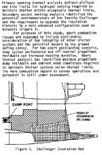
Also, don't forget about about the aft compartment TPS modification that Challenger was due for after STS-51L, description attached. So a change from the smooth FRSI to the quilted AFRSI. Just one of the many changes Challenger had in front of her once she returned from STS-51L.
Attachments
The holes (both sides) were always there, but they had covers. According to DaveS above, only the LH cover ever came off and was replaced by the umbilical plate (or exposed it?). Not sure how this would be handled overall, but what we have now (textures have the cover, and the plate pokes thru when used) seems OK. :shrug:
So in summary: The textures will show the cavity only on the port side of both Atlantis (all versions) and Challanger. As far as Challenger TPS scheduled modifications I understand the changes were to be made post STS-51L (last flight) hence there is no change to be applied to the texture in the related area.
Correct?
Correct?
So in summary: The textures will show the cavity only on the port side of both Atlantis (all versions) and Challanger. As far as Challenger TPS scheduled modifications I understand the changes were to be made post STS-51L (last flight) hence there is no change to be applied to the texture in the related area.
Correct?
If by cavity you mean the umbilical plate, then IMO no. There were holes in the fuselage on both sides on all vehicles (I think for the OMS kit), but they had a cover (which is what is visible in the photos). For the Centaur they took off the cover off the port side and put in there the umbilical plate where the RBUS would connect.
Currently in SSU, the umbilical plate is part of the Centaur piping, and pokes out where the cover is. (a totally acceptable solution for me)
Now, would the cover return after Centaur to hide the plate, or would the plate be exposed from then on? I don't know, but I'd say the cover would return.
So, IMO the textures should show the covers only (both sides), and the umbilical plate should be handled in the Centaur stuff.
- Joined
- Feb 4, 2008
- Messages
- 9,761
- Reaction score
- 1,029
- Points
- 203
I'm not so sure about this. One huge noticeable example of this was the SILTS pod, originally only a temporary thing but ended up as a permanent part. The actual experiment was removed after STS-40 in 1991 but after a series of wind tunnel experiments and aero-effects analysis, they decided to leave the pod in place.Now, would the cover return after Centaur to hide the plate, or would the plate be exposed from then on? I don't know, but I'd say the cover would return.
I'm pretty sure that they would just have left it on to to reduce turn-around time.
IMO, the key info here that we are missing is: (1) does the cover go over the plate, or (2) does the plate have to be removed to bolt the cover again?I'm pretty sure that they would just have left it on to to reduce turn-around time.
If it's (1), then yes, they probably would leave it, at least for a while. But if it is (2), then I think they would put the cover back, even if just to keep the plate "cleaner".
Anyway, I don't see the point of having a new texture(s) with just the plate being different. I think we can deal with it in much cheaper ways.
- Joined
- Feb 4, 2008
- Messages
- 9,761
- Reaction score
- 1,029
- Points
- 203
Based on my research, the plate replaced the cover entirely. I have attached a photo of the OASIS installation into the payload bay of Discovery for STS-26R which shows the inside of the left payload umbilical well with the standard cover installed.IMO, the key info here that we are missing is: (1) does the cover go over the plate, or (2) does the plate have to be removed to bolt the cover again?
If it's (1), then yes, they probably would leave it, at least for a while. But if it is (2), then I think they would put the cover back, even if just to keep the plate "cleaner".
Attachments
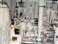
Based on my research, the plate replaced the cover entirely. I have attached a photo of the OASIS installation into the payload bay of Discovery for STS-26R which shows the inside of the left payload umbilical well with the standard cover installed.
That actually looks like it has an internal cover... :uhh: It seems too close to the PLB liner to be in the fuselage wall.
Similar threads
- Replies
- 36
- Views
- 13K
- Replies
- 32
- Views
- 12K
- Replies
- 2
- Views
- 4K
- Replies
- 13
- Views
- 6K