That's awesome, and pretty much exactly what I'd like to make myself. Can you make or do you have a walkthrough of how you made it? And what exactly did you change in the NASSP source code to make it work? I'd love to build one for myself.
Thanks,
now I have to do what "I like the most" about my projects: Documenting it :lol:
Basic layout is as following:
- One Arduino (Diecimila) board, which I had lying around
- Four MAX7219 (Serially Interfaced, 8-Digit LED Display Drivers)
- 21 Seven segment displays + 3 "Sign" 7Segment displays
- Several LEDs for status lights and "static" lights (NOUN,VERB,PROG)
- One Keyboard controller IC salvaged from an old PS/2 Keyboard
- 19 Keys connected to the Keyboard encoding IC
A general "design rule" was, that the DSKY should *not* need any additional powers supply and can be powered over a standard USB (2.0) port. Currently it draws 375mA max. and about 200 mA avg. (changing the keyboard encoding hardware might reduce the consumptions a far bit lower. Without keboard IC powered it draws 96 mA less!).
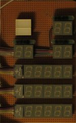
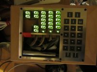
All the 7-Segment displays were combined in blocks of 6 7-Segments controlled by one MAX7219 (thus needing four of them). Free outputs of the MAX7219 are used to drive the status lights.
All this is currently done on breadboard (see Attachment), so no PCB layout available, sorry
The four MAX7219s are daisy-chained and connected via the SPI bus to the Arduino.
The keyboard controller (PS/2 connector) is connected to the Arduino board, too.
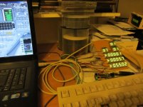
On the software side the microcontroller code just waits for serial data from the PC-AGC (channel 010, 011 and 013) and encodes them. Those data is transferred via SPI to the MAX7219s.
The second task is to wait for keyboard interrupt and send the transformed message serialized to the PC(-AGC).
Some "special" code was added in some "spare nouns" to control the display intensity.
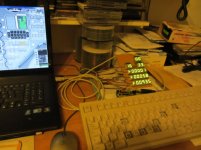
On the PC side (NASSP) all that is done is to tap the channels 010, 011 and 013 and send that data via a serial port (USB Serial port) and to listen for data on that serial port to be inserted into the keyboard routine.
Basically the same as on the microcontroller but in the opposite direction
")
I would really like to have more instructions available and I planned to make a PCB layout so that the soldering is much more easy, but I've not found the time for that, sorry.
One thing I started with was a PCB-Layout for one single Register (see 2nd attachment), but that has never seen the light of day now, so it could contain errors.
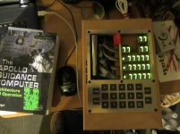
Last but not least I went to the local polytechnic university and let them mill the frontpanel for me. It's always nice when you have "connections" :lol:
(see 3rd attachment)


")
 rly:
rly: