Yes, exactly. USB between buttons and RPi. And there are many options:
1) Buttons => Leonardo => USB => RPi
2) Buttons => disassembled USB keyboard => USB RPi
3) Buttons => RPi GPIO.
Only ~24 buttons because not enough GPIO. Can be used in my project.
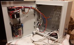
4) Buttons => Keypad matrix wiring => RPi GPIO
Can be used both by your and my projects. Already implemented code in python, but not tested yet.
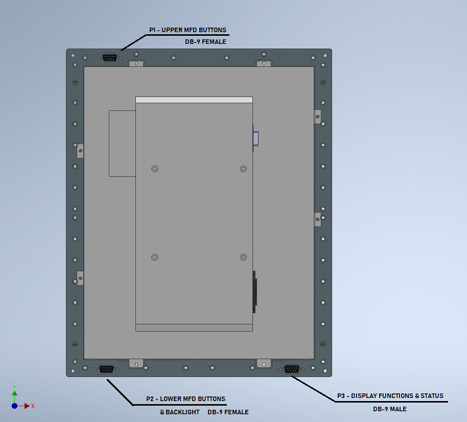
There are many options how to wire buttons. To make PythonVNC viewer code more easy, it is recommended to wire separate matrix block for each MFD.
I really don't want to implement two VNC objects into single Python code. Instead it is possible to make 2 separate PythonVNC applications who have almost similar code.
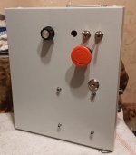
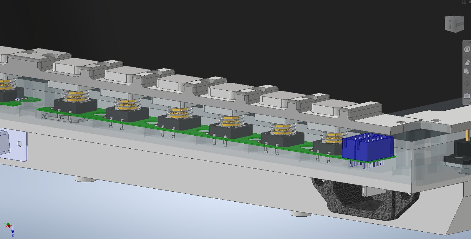
Regarding buttons. No, there aren't any click and nice feeling. They have light press force. I purchased some buttons in local electronic store to get an idea and feeling. PS15BBK was best for me. Now I need some free time to solder and test buttons with RPI in matrix wiring.
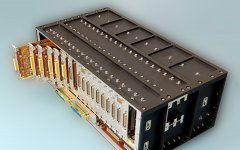
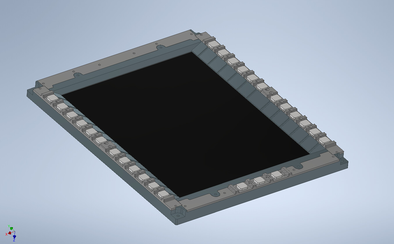
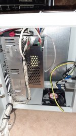
Just found on internet my LCD TV: https://www.globalmediapro.com/dp/A02X08/Swit-M-1050B-3-x-5-inch-LCD-Monitor/
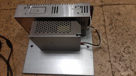
I disassembled and took one module out of metal frame for experiments.
Thanks for help offering. Will write you PM if need some CAD help.
1) Buttons => Leonardo => USB => RPi
2) Buttons => disassembled USB keyboard => USB RPi
3) Buttons => RPi GPIO.
Only ~24 buttons because not enough GPIO. Can be used in my project.
4) Buttons => Keypad matrix wiring => RPi GPIO
Can be used both by your and my projects. Already implemented code in python, but not tested yet.
There are many options how to wire buttons. To make PythonVNC viewer code more easy, it is recommended to wire separate matrix block for each MFD.
I really don't want to implement two VNC objects into single Python code. Instead it is possible to make 2 separate PythonVNC applications who have almost similar code.
Regarding buttons. No, there aren't any click and nice feeling. They have light press force. I purchased some buttons in local electronic store to get an idea and feeling. PS15BBK was best for me. Now I need some free time to solder and test buttons with RPI in matrix wiring.
Just found on internet my LCD TV: https://www.globalmediapro.com/dp/A02X08/Swit-M-1050B-3-x-5-inch-LCD-Monitor/
I disassembled and took one module out of metal frame for experiments.
Thanks for help offering. Will write you PM if need some CAD help.
Last edited:
")


")
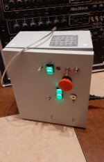
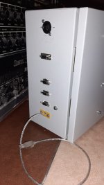
 But they look gorgeous, dont they??