-
ORBITER-FORUM will be temporarily closed at 2026-07-23 18:00 UTC while we complete some OF maintenance tasks. The amount of downtime is expected to take up to one hour, but probably less.
You are using an out of date browser. It may not display this or other websites correctly.
You should upgrade or use an alternative browser.
You should upgrade or use an alternative browser.
SSU Development Thread (2.0 to 3.0)
- Thread starter Urwumpe
- Start date
- Status
- Not open for further replies.
I'm correcting the launch position of the payload bay cameras, and noticed the scenario entry is called "PLBD_CAM", and I think the D in there is a typo. "PLDB_CAM" or "PLB_CAM" would be fine. Can anybody "prove" this isn't a typo?
- Joined
- Feb 6, 2008
- Messages
- 38,938
- Reaction score
- 3,937
- Points
- 203
- Location
- Wolfsburg
- Preferred Pronouns
- Sire
I'm correcting the launch position of the payload bay cameras, and noticed the scenario entry is called "PLBD_CAM", and I think the D in there is a typo. "PLDB_CAM" or "PLB_CAM" would be fine. Can anybody "prove" this isn't a typo?
Don't we have multiple cameras in the PLB, labeled A to D?
Don't we have multiple cameras in the PLB, labeled A to D?
Yes, but the orientation of all those cameras is saved under the paremeter "PLBD_CAM". If it was to save the positions individually it would use names like "PLB_CAM_A", etc, and not "PLBA_CAM".
---------- Post added at 11:22 PM ---------- Previous post was at 03:07 PM ----------
I'm pleased to report that the problem with panel A8 seems to be gone. Probably somewhere in the last changes, something was made that "fixed" this. I'll know more when I go back and check the what/when/how (right now I'm "stuck" until the TAA changes are committed).
- Joined
- Oct 20, 2010
- Messages
- 832
- Reaction score
- 1
- Points
- 16
- Location
- Alamogordo
- Website
- www.h-10-k.com
In the final TAA versions, Two IIRC
#1 two hard hatches, one soft
#2 4 hard hatches, 3 soft
All animated or removed?
Adjust fire over!
Maybe a nice illustration with a legend might help.
#1 two hard hatches, one soft
#2 4 hard hatches, 3 soft
All animated or removed?
Adjust fire over!
Maybe a nice illustration with a legend might help.
I have a proposal to "minimize the effects" of ticket #100 (Aft Keyboard out of position): I could manually shift aft (Z axis) the vertices of each key in there, thus fixing the sideways error in the panel. To fix the up/down error, one would have to change both the X and Y coordinates very carefully to keep the keyboard on the panel surface, and to do that manually would be very time consuming so I'll just leave that to the experts and their tools. :lol:
So, any concerns over this?
So, any concerns over this?
- Joined
- Feb 6, 2008
- Messages
- 38,938
- Reaction score
- 3,937
- Points
- 203
- Location
- Wolfsburg
- Preferred Pronouns
- Sire
I have a proposal to "minimize the effects" of ticket #100 (Aft Keyboard out of position): I could manually shift aft (Z axis) the vertices of each key in there, thus fixing the sideways error in the panel. To fix the up/down error, one would have to change both the X and Y coordinates very carefully to keep the keyboard on the panel surface, and to do that manually would be very time consuming so I'll just leave that to the experts and their tools. :lol:
So, any concerns over this?
Can't we just use better coordinates for the action area?
Can't we just use better coordinates for the action area?
That will have to be updated as well. But as the keyboard texture is "linked" to the keyboard meshes (one group per key), those groups have to be moved. Right now the keyboard is off both on its top/down position as well as its left/right position (the bigger error), this in relation to the panel. This fix would remove most/all of the current bigger error.
- Joined
- Feb 6, 2008
- Messages
- 38,938
- Reaction score
- 3,937
- Points
- 203
- Location
- Wolfsburg
- Preferred Pronouns
- Sire
That will have to be updated as well. But as the keyboard texture is "linked" to the keyboard meshes (one group per key), those groups have to be moved. Right now the keyboard is off both on its top/down position as well as its left/right position (the bigger error), this in relation to the panel. This fix would remove most/all of the current bigger error.
I would still prefer leaving mesh editing to the graphics department - they should know what they are doing.
How about an new release candidate today?
I agree with you about fixing the top/down error, as that needs changes on 2 axis, and it must be done very well to keep the keyboard on the panel surface. What I'm proposing is subtracting a certain fixed amount from one of the axis (the Z axis), and because of the orientation of the panel, this would shift the keyboard aft, in a parallel plane to the panel surface. IMO it's safe, but if there are concerns then I'll just go do something else.I would still prefer leaving mesh editing to the graphics department - they should know what they are doing.
Sounds good, but I think we should wait for the TAA (shouldn't be long now).How about an new release candidate today?
I propose having 3 meshes.
1. TAA with hatch and cover
2. ExAirlock no ODS would have the covers and ring handrail
3. ISSAirlock would have the top cover and ring handrail removed. That way the ODS could be added, without changing it's mesh or animations.
1. TAA with hatch and cover
2. ExAirlock no ODS would have the covers and ring handrail
3. ISSAirlock would have the top cover and ring handrail removed. That way the ODS could be added, without changing it's mesh or animations.
- Joined
- Feb 6, 2008
- Messages
- 38,938
- Reaction score
- 3,937
- Points
- 203
- Location
- Wolfsburg
- Preferred Pronouns
- Sire
I agree with you about fixing the top/down error, as that needs changes on 2 axis, and it must be done very well to keep the keyboard on the panel surface. What I'm proposing is subtracting a certain fixed amount from one of the axis (the Z axis), and because of the orientation of the panel, this would shift the keyboard aft, in a parallel plane to the panel surface. IMO it's safe, but if there are concerns then I'll just go do something else.
Well, then just put my concern on the record: I think that such editing is, regardless how simple it is, an unnecessary error source. We have people who can do this, without having to edit numbers. Just one small typo there and we have new mesh errors. And it also takes you much more time to do this.
Sounds good, but I think we should wait for the TAA (shouldn't be long now).
Its OK, then I will delay it and work on the SSUWorkbench. XAML looked way easier when everything worked. Can somebody tell me why a "3*" column is smaller than a "1*" column?
I propose having 3 meshes.
1. TAA with hatch and cover
2. ExAirlock no ODS would have the covers and ring handrail
3. ISSAirlock would have the top cover and ring handrail removed. That way the ODS could be added, without changing it's mesh or animations.
If we need different meshes for the ExAL, couldn't the ODS already be attached to its ExAL? This way there would be just 2 meshes instead of 3.
BTW, for Mir and ISS dockings wasn't the ODS/ExAL the same? If so then it shouldn't be called "ISSAirlock" but maybe "ExAirlock_ODS" or something similar.
---------- Post added at 02:14 PM ---------- Previous post was at 02:04 PM ----------
I put the idea forward as I think I could do it safely. It wasn't a complete fix (that I think could be unsafe to do manually), but it would look much better than it is now. It was simply a single-axis subtraction on 128 vertices, but as most share the same value, there would be just 5 different numbers to deal with.Well, then just put my concern on the record: I think that such editing is, regardless how simple it is, an unnecessary error source. We have people who can do this, without having to edit numbers. Just one small typo there and we have new mesh errors. And it also takes you much more time to do this.
But like I said, I'll not go against the will of the group, so this is a mute discussion now.
The TAA is the 3rd mesh. If you attach the ODS to the airlock, then there would be a need, to update the animations. For Mir the blanket material for the ODS would have to be changed to orange.
You could call it StnAirlock
You could call it StnAirlock
- Joined
- Feb 4, 2008
- Messages
- 9,758
- Reaction score
- 1,028
- Points
- 203
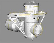
Another change between the two is the External Airlock truss. For the Mir missions it was outfitted with a second Trajectory Control Sensor (TCS) as well as two cameras, one for the Soyuz docking target on Kristall and one for the Buran docking target on the same module.The TAA is the 3rd mesh. If you attach the ODS to the airlock, then there would be a need, to update the animations. For Mir the blanket material for the ODS would have to be changed to orange.
You could call it StnAirlock

The TAA is the 3rd mesh. If you attach the ODS to the airlock, then there would be a need, to update the animations. For Mir the blanket material for the ODS would have to be changed to orange.
OK, do what you have to do.
As in Standard Airlock?You could call it StnAirlock
Another change between the two is the External Airlock truss. For the Mir missions it was outfitted with a second Trajectory Control Sensor (TCS) as well as two cameras, one for the Soyuz docking target on Kristall and one for the Buran docking target on the same module.
Couldn't those extra parts be added to the Mir ODS mesh? That way they would only show when the Mir ODS was used.
EDIT: Oh wait, we don't have/need a Mir ODS mesh.... could it then be added as a separate group on the single ODS mesh then? We would show/hide that group as needed. And the ODS texture change for Mir could be done via code, right?
Last edited:
- Status
- Not open for further replies.
Similar threads
- Replies
- 12
- Views
- 4K
- Replies
- 21
- Views
- 19K
- Replies
- 374
- Views
- 89K
- Replies
- 7
- Views
- 4K
- Replies
- 143
- Views
- 25K