You are using an out of date browser. It may not display this or other websites correctly.
You should upgrade or use an alternative browser.
You should upgrade or use an alternative browser.
Project Energia 5V Heavy Launch Vehicle
- Thread starter N_Molson
- Start date
- Joined
- Feb 6, 2008
- Messages
- 38,965
- Reaction score
- 3,937
- Points
- 203
- Location
- Wolfsburg
- Preferred Pronouns
- Sire
Oh...I have forgotten I wanted to reply here. ?
You need the rotation matrix actually just for one thing: you take the CONTROL vector that describes pitch and yaw commands for each booster in body coordinates of the launcher, and then rotate those into the body coordinates of the booster. And these commands can then be turned into engine gimbal commands by the booster.
For example, x is pitch, y is yaw and z is roll. Your matrix would then not change the roll command, but rotate pitch and yaw commands for each booster into the coordinates of the booster vessel - and you can use just one booster vessel class for all four stages.
Theoretically, you can also give the boosters roll commands. But then, you should be able to select the engine chamber that moves by a bitmask (or similar) to make sure, only the outmost chambers are moving for roll (all engines would result in less roll torque since the inner engines would counter the torque partially)
This way, you can still use the code for the engines for all boosters and the core, but can also quickly change the control configuration, for example for flying a separation maneuver with the boosters for safer separation.
I tried to multiply the matrix in code, but I get crazy results. Can you check it ? Thanks.
I used the matrix I posted on post #108
Pitch_sum is my input level a number between -1 and 1.
C++:auto v = _V(Pitch_sum*sin(0.0349066), Pitch_sum*sin(0.0349066), 1-(Pitch_sum*sin(0.0349066))); auto m = _M(cos(0.0349066)+0.5*(1-cos(0.0349066)), 0.5*(1-cos(0.0349066))-0*sin(0.0349066), 0*(1-cos(0.0349066))+0.707106*sin(0.0349066), 0.5*(1-cos(0.0349066))+0*sin(0.0349066), cos(0.0349066)+0.5*(1-cos(0.0349066)), 0*(1-cos(0.0349066))-0.707106*sin(0.0349066), 0*(1 - cos(0.0349066))-0.707106*sin(0.0349066), 0*(1 - cos(0.0349066))+ 0.707106*sin(0.0349066), cos(0.0349066)+0*(1 - cos(0.0349066))); auto r = mul(m, v);
I used the matrix I posted on post #108
Pitch_sum is my input level a number between -1 and 1.
Last edited:
- Joined
- Feb 6, 2008
- Messages
- 38,965
- Reaction score
- 3,937
- Points
- 203
- Location
- Wolfsburg
- Preferred Pronouns
- Sire
Tooo many digits, I can do that tomorrow after some sleep. But I am sure already, that you converted 45° wrong into radians: PI/4 = 0.7854. Your number is equivalent to 2° again.
360° = 2 * PI
180° = PI
90° = PI/2
45° = PI/4
2° = PI/90
1° = PI/180
360° = 2 * PI
180° = PI
90° = PI/2
45° = PI/4
2° = PI/90
1° = PI/180
But the 45° angle should be for the axis vector u which is _V(0.707,0.707,0) ? Again, I'm refering to post #108.
The angle 'Theta' should be equal to 2° (because my transformation is a +-2° rotation on a 45° tilted axis), no ?
Thanks, take your time, meanwhile I'll work on the meshes, I have to begin to make proper engine models for the upper stages
The angle 'Theta' should be equal to 2° (because my transformation is a +-2° rotation on a 45° tilted axis), no ?
Thanks, take your time, meanwhile I'll work on the meshes, I have to begin to make proper engine models for the upper stages
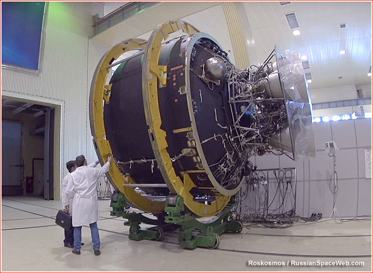
Starting to work on Stage 3. I must say there is very little data to work with, so there will be some "artistic licence", using Anatoly Zak renders as a reference. That stage is supposed to be an expanded enhanced Angara upper stage (aka URM-2V).
Here is the URM-2 currently in use, note that the engine (RD-0146) is completely different.
In contrast the URM-2V is supposed to use 2x RD-0150, a single-chambered LOX/LH2 engine (not unlike the US Centaur RL-10). That engine might not even exist yet - or is classified.


Here is the URM-2 currently in use, note that the engine (RD-0146) is completely different.
In contrast the URM-2V is supposed to use 2x RD-0150, a single-chambered LOX/LH2 engine (not unlike the US Centaur RL-10). That engine might not even exist yet - or is classified.
Last edited:
Also worked on the boosters attachments. They were a bit far from the core, fixed that too. I used Angara 5 assembly pics as a reference, its safe to say those rockets use the same technology.

You need to check the normals of the nozzles. Also the struts connecting the boosters to the core, they seem to have a cap at their ends, which should be uneeded because of the black connections, and is making the light uneven in the struts.Also worked on the boosters attachments. They were a bit far from the core, fixed that too. I used Angara 5 assembly pics as a reference, its safe to say those rockets use the same technology.
n72.75
Seize the means of computation
Orbiter Contributor
Addon Developer
Tutorial Publisher
Donator
- Joined
- Mar 21, 2008
- Messages
- 2,873
- Reaction score
- 1,716
- Points
- 128
- Location
- Saco, ME
- Website
- mwhume.space
- Preferred Pronouns
- he/him
Yeah, could well be the normal. They look a bit back-lit.

You can select the faces inside the nozzle and then recalculate the normals. (I see you already fixed thisGood catch, yep forgot the caps. I must say there is something weird with the shadows inside the nozzles, will look into that.
") )
)If you have a bottom surface, connecting the inside and outside surfaces of the nozzle, then it will also cause weird lighting. You can selected it, split it into a new group, and them merge back into the main nozzle mesh. The idea here is that if you have vertices that are used by, e.g., the inside surface and the bottom surface, then the light will blend across both faces, which is very useful in curved areas, but in sharp places does not look good.
Visual representation of a section of the nozzle:
(inside) | . _____ . | (outside)
^^ dots = vertices; lines = faces
With the split, vertices will be created for the ends of the sides and for the bottom, thus their lighting will be independent of each other. (merging the resulting groups does not merge the vertices, for that you would have to do the "Remove Doubles" command.
I see what you mean, I think something like that is going on on the short "boattail" section of the boosters, lighting don't match the boosters body. I'll try that.
Edit : fixed by merging vertices, looks better.
Edit : fixed by merging vertices, looks better.
Last edited:
Some more work on stage 3 :

Have to add some more plumbing, the engine gimbal actuators and some struts to attach loose parts to the octogonal frame. And wires for electrics/electronics.
Have to add some more plumbing, the engine gimbal actuators and some struts to attach loose parts to the octogonal frame. And wires for electrics/electronics.

Those "red wires" and "big copper plugs" are of course a simplification of the complex data/electrical network you have on such a huge rocket, but I'll make sure those plugs are aligned with those of the stage above/below and "connect" as they should, and that the whole stack is covered : the capsule at the top needs access to the first stage 5 engines parameters (for monitoring, maybe emergency manual control and for triggering the LES in case of anomaly).
Added the gimbal actuators to the engines (2 per engine for 2-axis control), quite a lot of work as I had to redesign the fuel ducts layout. Also each engine is mounted on a rotula. Will be a loooot of fun to animate ! Also added transducer boxes. Still have the wiring to do. But its taking shape.

Took some time to make the wiring, had to learn a couple of new Blender things to get a decent result.
Here we have the wires coming from the lower stage plug (the interstage), going to the "computer box" (which will be connected to the engines) and going to the electric gutter plug (which will be connected to the upper stage plug and to the top tank pressure probe).

Here we have the wires coming from the lower stage plug (the interstage), going to the "computer box" (which will be connected to the engines) and going to the electric gutter plug (which will be connected to the upper stage plug and to the top tank pressure probe).


Similar threads
- Replies
- 10
- Views
- 4K
- Replies
- 19
- Views
- 8K
- Replies
- 34
- Views
- 9K