OK, so it would be some kind of fireproof insulation ? It makes some sense as Proton stages rely on "hotfire" ignition, which means that there is always some backfire during the few seconds.
You are using an out of date browser. It may not display this or other websites correctly.
You should upgrade or use an alternative browser.
You should upgrade or use an alternative browser.
Project Mir station complex / UR-500 family
- Thread starter MaxBuzz
- Start date
- Joined
- Feb 6, 2008
- Messages
- 38,965
- Reaction score
- 3,937
- Points
- 203
- Location
- Wolfsburg
- Preferred Pronouns
- Sire
OK, so it would be some kind of fireproof insulation ? It makes some sense as Proton stages rely on "hotfire" ignition, which means that there is always some backfire during the few seconds.
Not for the third stage, which has no vent ports in the interstage surrounding it. I think it is actually just a thermal cover to prevent freezing or early vaporization of the fuel during operation.
Also look here:
The third stage of Proton rocket
The third stage of the Proton rocket by Anatoly Zak
www.russianspaceweb.com
The cover is still on the engine WHILE the stage is installed into its fairing.
Also, the cover could protect the engine from the exhaust and heat flux of the steering engines, another possibility.
Oh yes that's right of course. I had that pic but "forgot" they were actually assembling the stack, that's the issue when you focus on details and "lose the big picture". Well, thanks, I'll see what I can do with Blender, the problem with cloth-like stuff is that it should always move a bit (no real wind that high but still acceleration)... 
- Joined
- Feb 6, 2008
- Messages
- 38,965
- Reaction score
- 3,937
- Points
- 203
- Location
- Wolfsburg
- Preferred Pronouns
- Sire
Oh yes that's right of course. I had that pic but "forgot" they were actually assembling the stack, that's the issue when you focus on details and "lose the big picture". Well, thanks, I'll see what I can do with Blender, the problem with cloth-like stuff is that it should always move a bit (no real wind that high but still acceleration)...
Oh, yeah and vibrations of course.
But trust me: Nobody will kill you if the textile is stiff like frozen laundry.
") We know that Orbiter isn't unlimited and we know that CPU and GPU time is precious.
We know that Orbiter isn't unlimited and we know that CPU and GPU time is precious.Maybe you can cheat something like that by using normal mapping and some clever tricks with the UV coordinates.
@Urwumpe : Yes, the best way to do it right now is probably through texture manipulation.
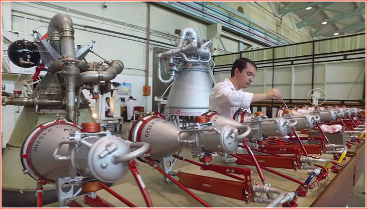
About the "red color = remove before flight", what do you think about those verniers ? Are all the red parts only there to keep moving parts in place ? Seems there is red stuff everywhere where there should be actuators / hardpoints, so I'm a bit confused...
About the "red color = remove before flight", what do you think about those verniers ? Are all the red parts only there to keep moving parts in place ? Seems there is red stuff everywhere where there should be actuators / hardpoints, so I'm a bit confused...
- Joined
- Feb 6, 2008
- Messages
- 38,965
- Reaction score
- 3,937
- Points
- 203
- Location
- Wolfsburg
- Preferred Pronouns
- Sire
Well, I am sure, it must get removed before installation or flight as well: One of the rods connects to the ring holding the nozzle cover in place, also all three rods prevent the vernier engine from rotating. The engines still need to be installed into the flight structure with the actuators.
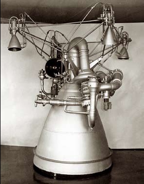
here you can find some small more info about the steering engine:
Note that this photograph above looks pretty different to the final state.
here you can find some small more info about the steering engine:
Note that this photograph above looks pretty different to the final state.
Yes I think they connect the actuators to the stage replacing the red parts step by step, and at this point the stage and the rocket is probably under electrical power up to the launchpad (the carrier train has huge AC/DC converters).


")
.gif")


First draft, the proportions should be good, I used the schematics provided above. Had the main engine ready, because it is 1/4th of the second stage one, but fixed and steered by the verniers. I'll see what I can do with the cover once the verniers are set, still have to figure how the actuators are actuated and articulated because I want them to animate properly. Then there's nothing really very complex on the stage body.
.png")
- Joined
- Feb 6, 2008
- Messages
- 38,965
- Reaction score
- 3,937
- Points
- 203
- Location
- Wolfsburg
- Preferred Pronouns
- Sire
First draft, the proportions should be good, I used the schematics provided above. Had the main engine ready, because it is 1/4th of the second stage one, but fixed and steered by the verniers. I'll see what I can do with the cover once the verniers are set, still have to figure how the actuators are actuated and articulated because I want them to animate properly. Then there's nothing really very complex on the stage body.
As usual for Russian vernier engines, tangentially. They are not Atlas vernier engines. Also, the rotation gimbal is coarsely at the center of thrust, contrary to the TVC of bigger rocket engines, which have an offset between the gimbal position and the center of thrust.
I was going to make my life even harder figuring out 2 gimbal axis per vernier that don't exist. You're right, there's no need for that. 2 engines control pitch, 2 control yaw, and you mix the inputs with roll. ?
@Urwumpe : so in the case of those verniers, they get their fuel/oxydizer through the pumps of the main engine, right ?
From Wiki :
There's no thing like like 4 independent verniers engines, there is 1x quad-chambered RD-0214 which shares the pumps with the main engine (RD-0212), right ?
From Wiki :
RD-0214 (GRAU Index: 8D811): An evolution of the RD-0207 engine, used as vernier engine of the RD-0212 propulsion module along the RD-0213. It has four combustion chambers that can gimbal 45 degrees in a single plane and allow the Proton third stage to have vector control.
There's no thing like like 4 independent verniers engines, there is 1x quad-chambered RD-0214 which shares the pumps with the main engine (RD-0212), right ?
- Joined
- Feb 6, 2008
- Messages
- 38,965
- Reaction score
- 3,937
- Points
- 203
- Location
- Wolfsburg
- Preferred Pronouns
- Sire
@Urwumpe : so in the case of those verniers, they get their fuel/oxydizer through the pumps of the main engine, right ?
No, they have their own pumps - see the link I send you from lpre.de, its in Russian, but maybe it help you understand this engine family. The proton usage is at the bottom of the page.
@Urwumpe : some more questions about the image below :

I think I got the rotation axis for the "tangential motion" (given the cross section of the stage is the circle).
Now what are "a" and "b" for ? If "b" an actuator (weird, that would go against the rotation axis) or maybe a placeholder for flexible ducts ? Would "a" really fly with the engine ? It looks a bit like a stand for me, but then it does not explain while the whole "b" thing is connected to it...
Also, where the "c" (orange square) is supposed to go ? It has to get some fuel/oxydizer from somewhere, alas we can't see the end of that pipe...
- Joined
- Feb 6, 2008
- Messages
- 38,965
- Reaction score
- 3,937
- Points
- 203
- Location
- Wolfsburg
- Preferred Pronouns
- Sire
Lets take a look here :
a is the mounting bracket for both flexible propellant lines for each steering engine. The fuel line goes into the nozzle end and cools the engine chamber, the oxidizer line is routed around the engine (pay attention to the steering engine right front of the picture)
b is just some support during integration
c is the oxidizer line going into the engine
Similar threads
- Replies
- 12
- Views
- 16K