Offtopic, but...
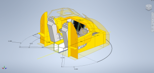
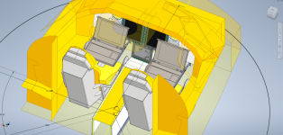
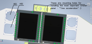
Yesterday I played with mesh file format (.msh) and wrote small program to convert mesh into .stl file. Now you can open it with you favorite 3D CAD software. For some reasons virtual cockpit it is mirrored on Y axis. Reason for this experiment is simple: now you can hack mesh and export forward windows and HUD in a way they are clean an can be feeded to separate HDMI outputs for simpit LCD displays or projectors. Still lot of work, including DeltaGlider code compiling and hacking, but it is small progress. Some technical details: group 129 (search for text: LABEL HUDDISP in deltaglider_vc.msh file) is HUD drawing surface. It contain 4 vertices and 2 triangles. By editing this group you can move HUD in cabin to any place you want.
I attached virtual cockpit converted into .stl files. Have fun with them in your 3D CAD software.
") Anyway, 270deg projector screen is my ultimate goal, but simple LCD/plasmas should work great without busting the bank. You can find good deals on those in the used market. Even for 32/42 inch TVs.
Anyway, 270deg projector screen is my ultimate goal, but simple LCD/plasmas should work great without busting the bank. You can find good deals on those in the used market. Even for 32/42 inch TVs.")


")
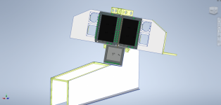
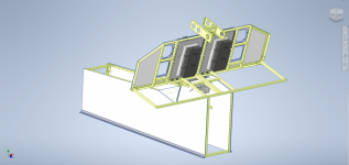
 Even 1 person cabin will not go thru doors. Need to sink about easy disassembly/transportation/assembly. Or... Special room/garage for simpit.
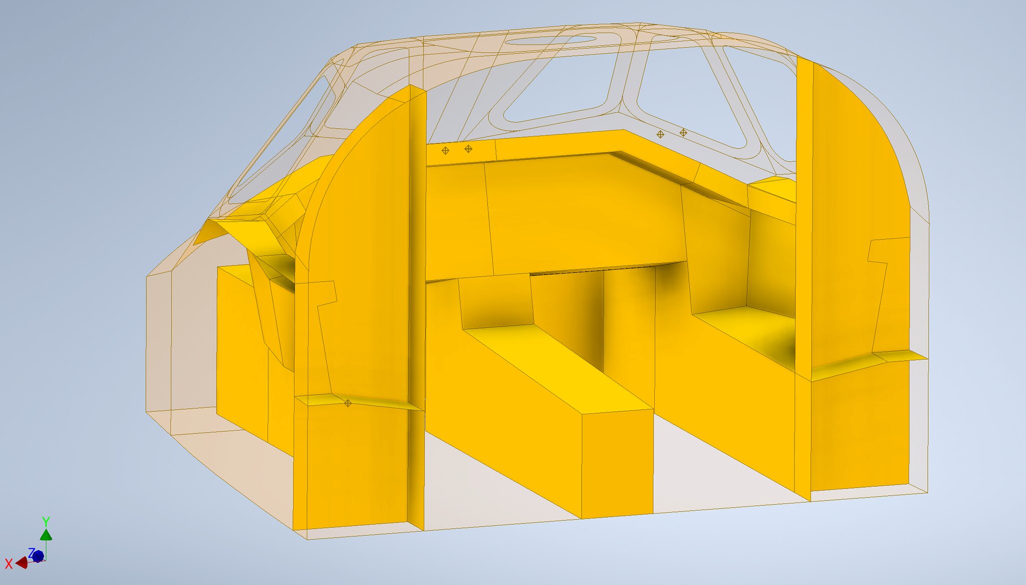

 .
.

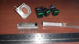
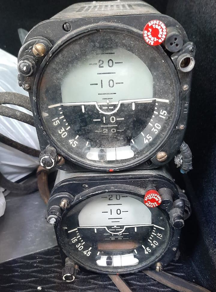
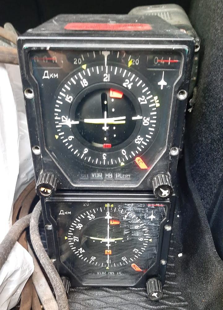
 I hope now I can clean them well and start measuring process..

 .
.