General Question Burn Vector view in an MFD

jedidia

shoemaker without legs
Addon Developer
Joined
Mar 19, 2008
Messages
11,324
Reaction score
2,805
Points
203
Location
between the planets
I wondered if the graphical representation of the burn vector views of IMFD or TransX or RendevouzMFD etc. are custom-made, or if they are already integrated somehow in the default MFD?

If not, I guess I have to use WinGUI functions to draw them, right?

---------- Post added 07-15-10 at 03:17 PM ---------- Previous post was 07-14-10 at 03:22 PM ----------

Ok, after looking some more into the matter it became clear to me that the Burn vector view isn't part of the MFD-class, so I'll have to do it myself. Now, as far as I could discern, Orbiter 2010 does provide its own interface for drawing operations, Sketchpad. I have so far failed to find any comprehensible examples for it, and my own experiments haven't really worked out. To be honest, I couldn't even define a sketchpad-object in my code, and I don't even know if I'm supposed to. In other words, I have no Idea how to use the thing, and so far haven't managed to draw a simple line or put some text in the MFD with it (the Windows GUI function seem to be much less complicated, but I want to do this right...)

If anyone has a short example, I'd be very glad.
 
Use the MFD template found from orbitersdk/samples/MFDTemplate/


Code:
void DrawBurnVectorView_SKP(Sketchpad *pkp, int width, int height, VECTOR3 _dv)
{
        VESSEL *vessel = oapiGetFocusInterface();
    
        Pen *pen1 = oapiCreatePen(1,1,dgreen); 
        Pen *pen2 = oapiCreatePen(1,1,green); 
        Pen *pen3 = oapiCreatePen(1,1,grey); 

        VECTOR3 thrustdir = unit(GetThrusterGroupDir_LH(vessel, maneuver.engine));

        VECTOR3 fore      = _V(0,0,1);
        VECTOR3 upwards   = _V(0,1,0);
        VECTOR3 side      = _V(1,0,0);

        vessel->GlobalRot(fore, fore);
        vessel->GlobalRot(upwards, upwards);
        vessel->GlobalRot(side, side);
        vessel->GlobalRot(thrustdir, thrustdir);

        fore    = unit(fore);
        side    = unit(side);
        upwards = unit(upwards);

        VECTOR3 prod = unit(crossp(thrustdir, _dv));
        double  ang  = angle(_dv, thrustdir);

        double roll  = -dotp(prod,fore)*ang;
        double yaw   = dotp(prod,upwards)*ang/PI;
        double pitch = dotp(prod,side)*ang/PI;

        skp->SetPen(pen1);

        skp->MoveTo(20,height/2);
        skp->LineTo(width/2 - 20, height/2);

        skp->MoveTo(width/2 + 20 ,height/2);
        skp->LineTo(width - 20, height/2);

        skp->MoveTo(width/2, 20);
        skp->LineTo(width/2, height/2 - 20);

        skp->MoveTo(width/2, height/2 + 20);
        skp->LineTo(width/2, height - 20);

        skp->MoveTo(width/2 - 5, height/2 - 45);
        skp->LineTo(width/2, height/2 - 35);

        skp->MoveTo(width/2 + 5, height/2 - 45);
        skp->LineTo(width/2, height/2 - 35);

        skp->Ellipse(width/2 - 90,height/2 - 90,width/2 + 90,height/2 + 90);
        skp->Ellipse(width/2 - 20,height/2 - 20,width/2 + 20,height/2 + 20);

        double f = 0.003;
        double xx = sqrt(fabs(yaw)+f)-sqrt(f);
        double yy = sqrt(fabs(pitch)+f)-sqrt(f);
        
        int x=(int)(xx * (double)width/2.0);
        int y=(int)(yy * (double)height/2.0);

        if (yaw<0.0) x=-x; if (pitch<0.0) y=-y;

        skp->SetPen(pen2);

        skp->MoveTo(width/2, height/2);
        skp->LineTo(width/2 + x , height/2 + y);

        if (abs(x)<4 && abs(y)<4) skp->SetPen(pen3);

        skp->MoveTo(width/2 + x - 16, height/2 + y);
        skp->LineTo(width/2 + x + 16, height/2 + y);

        skp->MoveTo(width/2 + x , height/2 + y - 16);
        skp->LineTo(width/2 + x , height/2 + y + 16);

        x=(int)(sin(roll)*35);
        y=(int)(cos(roll)*35);

        int x2=(int)(sin(roll+12*RAD)*25);
        int y2=(int)(cos(roll+12*RAD)*25);

        int x3=(int)(sin(roll-12*RAD)*25);
        int y3=(int)(cos(roll-12*RAD)*25);

        skp->SetPen(pen2);
        if (fabs(roll)<0.1) skp->SetPen(pen3);

        skp->MoveTo(width/2 + x3 , height/2 - y3);
        skp->LineTo(width/2 + x , height/2 - y);
        skp->MoveTo(width/2 + x2 , height/2 - y2);
        skp->LineTo(width/2 + x , height/2 - y);
        
        oapiReleasePen(pen1);
        oapiReleasePen(pen2);
        oapiReleasePen(pen3);
}
 
W00t!

thanks a lot, Jarmonik! I only took a brief look at the template, because I expected it to be pretty bare, and was searching around in the TransX source code instead, which is a bit over my head. This will help me along quite some way!
 
You know, I looked at the MFD template from the orbiter SDK again, and it seems you and I have a different version of it, because mine doesn't have a vector view...

At first I thought I should be fine with the code you posted above, but it seems to reference quite a lot of functions of that example MFD, so it would be good to have the whole code. Could you tell me where you got that code from? One question on the sideline: what are the exact dimensions of an MFD screen?
 
Last edited:
The code is from LTMFD. The dimensions of MFD screen will depend about screen resolution and panel scaling. MFD will receive the dimensions in a MFD class constructor.

Code:
VECTOR3 GetThrusterGroupDir_LH(VESSEL *ship, THGROUP_TYPE engine)
{
    VECTOR3 d, dir=_V(0,0,0);
    double tot = 0.0;
    int i, c = ship->GetGroupThrusterCount(engine);
    
    for (i=0;i<c;i++) {
        THRUSTER_HANDLE th=ship->GetGroupThruster(engine,i);
        ship->GetThrusterDir(th,d);
        double thr = ship->GetThrusterMax0(th);
        tot += thr;
        dir += (unit(d) * thr);
    }
    return dir/tot;
}

LTMFD is a closed source project therefore I will post no more source codes.
 
LTMFD is a closed source project therefore I will post no more source codes.

ah! From what you wrote above, I had the impression that you got that code from the MFD template in the SDK. I didn't realise that it's actually from your own project. Thanks a lot for sharing it, I'll try to make the best I can of it! :thumbup:

But the still rather example-less nature of the sketchpad is giving me a hard time. Currently I'm wondering about where to get a surface handle from to create it. I searched all over the api documentation, but I have not yet found how to either get a surface handle from an MFD, or create one and link it with the MFD.
 
This code is from the MFDTemplate. It's showing how you receive a pointer into the sketchpad and how to use it.

Code:
// Repaint the MFD
bool MFDTemplate::Update (oapi::Sketchpad *skp)
{
    Title (skp, "MFD Template");
    // Draws the MFD title

    skp->SetFont (font);
    skp->SetTextAlign (oapi::Sketchpad::CENTER, oapi::Sketchpad::BASELINE);
    skp->SetTextColor (0x00FFFF);
    skp->Text (W/2, H/2,"Display area", 12);
    skp->Rectangle (W/4, H/4, (3*W)/4, (3*H)/4);

    // Add MFD display routines here.
    // Use the device context (hDC) for Windows GDI paint functions.

    return true;
}

If this code is different than the one you have then you may need to download the latest beta of the orbiter.
 
Indeed it is different. My MFD Template doesn't use the sketchpad... So, the Sketchpad doesn't have to be created, it is overloaded from orbiter itself into the update function. Well, that makes the whole buisness a lot more easy!

thanks a lot for your help! I should be able to get it done by myself now. And thanks a lot for all that code!

just on the sideline, does "LT" in LTMFD by chance stand for "Low Thrust"?

---------- Post added at 02:26 PM ---------- Previous post was at 07:17 AM ----------

Right, It's going very well. Thanks a lot for your code Jarmonik, it's very helpfull, and Sketchpad is pretty nice to use once you get the hang of it.

Now there is one question I have left, and I'm not exactly sure if anybody can answer it except Martin. Since this is for an interstellar project, It would be nice to know which alignement the global coordinate system of the solar system in Orbiter has relative to the galactic plane and center (i.e. What direction is X+Y+Z+?). I'd imagine the Z axis is in a right angle to the ecliptic, but what about the other two? I'm currently conducting some messuring, but until I identify the right stars and do my trigonometry, maybe someone knows the exact numbers?
 
Last edited:
just on the sideline, does "LT" in LTMFD by chance stand for "Low Thrust"?

No, the LT in LTMFD stands for Lunar Transfer.
 
*sigh* me and euler transformations... it's a tragic story I'm afraid. I get the basic concept, but I'm allways having trouble with the math behind it.

Basically, I'm currently having a Vector containing the position of the target point. From Orbiter, I'm getting euler angles, and after two hours of reading tutorials about euler angles, rotation matrixes and quaternions I haven't really understood a bit of the whole buisness. Ok, I understand perfectly well now what Euler angles are, but I don't seem smart enough to get the whole concept of rotation matrixes.

Anyways, what I'd have to do to solve my problem (at least I hope so) is converting the Global Orientation of my vessel to a normalized Vector. Can somebody tell me how to do that?
 
Basically, I'm currently having a Vector containing the position of the target point. From Orbiter, I'm getting euler angles, and after two hours of reading tutorials about euler angles, rotation matrixes and quaternions I haven't really understood a bit of the whole buisness. Ok, I understand perfectly well now what Euler angles are, but I don't seem smart enough to get the whole concept of rotation matrixes.

I can try to explain it to you if you like, but it could be a long way depending on your knowledge of basic trigonometry and vector calculation.

Anyways, what I'd have to do to solve my problem (at least I hope so) is converting the Global Orientation of my vessel to a normalized Vector. Can somebody tell me how to do that?

AFAIK, it can be done with VESSEL::GlobalRot(_V(0,0,1), OutputVector). If you are interested in vector calculus regarding target pointing, you can take a look at the JumpDriveMFD code. The MFD uses a simple text-oriented target finder, the appropriate code is in the JumpDriveMFD.cpp file, line 511 ff.

regards,
Face
 
I can try to explain it to you if you like, but it could be a long way depending on your knowledge of basic trigonometry and vector calculation.
Those are both no problem, but I don't get how to use them weird matrices... what to multiply with what in which situation??

AFAIK, it can be done with VESSEL::GlobalRot(_V(0,0,1), OutputVector).

oh, nice. Let's see if that solves my problem...
 
Those are both no problem, but I don't get how to use them weird matrices... what to multiply with what in which situation??

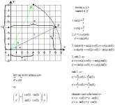
Ok, so let us start with a simple 2D model and some basic relationships (click the picture):
rotmat.PNG
5263

Do you see the relation between the rotation of a point - given in cartesian coordinates - around a certain axis and the 2x2 rotation matrix here? If so, we can go on with expanding this model to 3D...

regards,
Face
 
Now there is one question I have left, and I'm not exactly sure if anybody can answer it except Martin. Since this is for an interstellar project, It would be nice to know which alignement the global coordinate system of the solar system in Orbiter has relative to the galactic plane and center (i.e. What direction is X+Y+Z+?). I'd imagine the Z axis is in a right angle to the ecliptic, but what about the other two? I'm currently conducting some messuring, but until I identify the right stars and do my trigonometry, maybe someone knows the exact numbers?
I am using this matrix to rotate from ecliptic (J2000) to galactic frame, but the accuracy may be low, since I derived it by visually matching an image to known positions (and I suspect that the image may have been distorted). Any suggestions for a more precise transformation are welcome!
Code:
    // rotation from galactic to ecliptic frame
    Matrix ecl2gal;
    double theta = 60.18*RAD;
    double phi = 90.02*RAD;
    double lambda = 173.6*RAD;
    double sint = sin(theta), cost = cos(theta);
    double sinp = sin(phi), cosp = cos(phi);
    double sinl = sin(lambda), cosl = cos(lambda);
    ecl2gal.Set (cosp,0,sinp, 0,1,0, -sinp,0,cosp);
    ecl2gal.premul (Matrix (1,0,0, 0,cost,sint, 0,-sint,cost));
    ecl2gal.premul (Matrix (cosl,0,sinl, 0,1,0, -sinl,0,cosl));
(Note that "Matrix" is Orbiter's private 3x3 matrix class. It's equivalent to the MATRIX3 API type.)
 
Do you see the relation between the rotation of a point - given in cartesian coordinates - around a certain axis and the 2x2 rotation matrix here? If so, we can go on with expanding this model to 3D...
I think I do... basicaly, it enables the calculation of the new coordinates without having to calculate the angle a first. I also start to realise how the data of a rotation matrix has to be used, but please, go on.

@Martin: thanks. Maybe I can give more precise data once I get this running, since I'll be able to check deviations, allthough I still have to do the alignement visually with the stars in Orbiter.
 
Last edited:
ooooook, from what Martin posted above, what I learned from Face and a bit more reading, I have constructed the following to rotate the coordinates of my star into the coordinate system of orbiter. I have no Idea if this is correct, I'm more considering this an excercise currently. Somebody please take a look and tell me how epic I failed:

Code:
//StarPos contains the coordinates of a star relative to the sun in the galactic frame. 
//The converted coordinates should be in ConvStarPos at the end.

//rotation about Z-axis
        ConvStarPos.X = (StarPos.X * cosf(phi)) - (StarPos.Y * sinf(phi));
        ConvStarPos.Y = (StarPos.X * sinf(phi)) + (StarPos.Y * cosf(phi));
        ConvStarPos.Z = StarPos.Z;
        StarPos = ConvStarPos;

//rotation about X-axis
        ConvStarPos.X = StarPos.X;
        ConvStarPos.Y = (StarPos.Y * cosf(theta)) - (StarPos.Z * sinf(theta));
        ConvStarPos.Z = (StarPos.Y * sinf(theta)) + (StarPos.Z * cosf(theta));
        StarPos = ConvStarPos;

//rotation about Y-axis
        ConvStarPos.X = (StarPos.X * cosf(lambda)) + (StarPos.Z * sinf(lambda));
        ConvStarPos.Y = StarPos.Y;
        ConvStarPos.Z = -(StarPos.X * sinf(lambda)) + (StarPos.Z * cosf(lambda));
        StarPos = ConvStarPos;
 
Last edited:
You are defining a rotation sequence Z-X-Y, while I had Y-X-Y. You may be able to define it that way, but then obviously all the angles have different meanings. Also, you switched the signs in your Y-rotation, so your lambda goes the opposite direction to mine.

If you have to rotate a lot of stars, it is more efficient to explicitly build the rotation matrix and apply it to each star position, than to apply the three separate rotations to each of them. (A matrix x vector multiplication has 9 scalar multiplications and 6 additions, while yours has 12 multiplications and 6 additions).

Edit: to debug your code, you can split the rotation in two parts: The phi and theta rotations should rotate the galactic north pole into place. It should end up at position RA=12h 51m 26.282s, Dec=+27° 07′ 42.01″ (in constellation Coma Berenices). Once that is correctly positioned, apply the lambda rotation, which is a rotation around the galactic north pole.
 
ooooook, from what Martin posted above, what I learned from the Face and a bit more reading, I have constructed the following to rotate the coordinates of my star into the coordinate system of orbiter. I have no Idea if this is correct, I'm more considering this an excercise currently. Somebody please take a look and tell me how epic I failed:

Code:
//StarPos contains the coordinates of a star relative to the sun in the galactic frame. 
//The converted coordinates should be in ConvStarPos at the end.

//rotation about Z-axis
        ConvStarPos.X = (StarPos.X * cosf(phi)) - (StarPos.Y * sinf(phi));
        ConvStarPos.Y = (StarPos.X * sinf(phi)) + (StarPos.Y * cosf(phi));
        ConvStarPos.Z = StarPos.Z;
        StarPos = ConvStarPos;

//rotation about X-axis
        ConvStarPos.X = StarPos.X;
        ConvStarPos.Y = (StarPos.Y * cosf(theta)) - (StarPos.Z * sinf(theta));
        ConvStarPos.Z = (StarPos.Y * sinf(theta)) + (StarPos.Z * cosf(theta));
        StarPos = ConvStarPos;

//rotation about Y-axis
        ConvStarPos.X = (StarPos.X * cosf(lambda)) + (StarPos.Z * sinf(lambda));
        ConvStarPos.Y = StarPos.Y;
        ConvStarPos.Z = -(StarPos.X * sinf(lambda)) + (StarPos.Z * cosf(lambda));
        StarPos = ConvStarPos;

You are not that far off. What you did there was a combined rotation:

Code:
ConvStarPos=Y(lambda)* ( X(theta)* ( Z(phi)*StarPos ) )
since vector operations are associative (but not always commutative!), you could write it as:

Code:
ConvStarPos=( Y(lambda)*X(theta)*Z(phi) ) *StarPos
You could have calculated the matrix combination first and then used the same rotation matrix for all points.

But Martin seems to use a different euler-angle notation, it seems to be YXY.

So, what Martin posted as translation matrix for conversion from Orbiter-frame to galactic frame seems to be this:
Code:
ecl2gal=(Y3(phi)*X3(theta))*Y3(lambda)

with

      | 1    0       0    |
X3(ß)=| 0  cos(ß)  sin(ß) |
      | 0 -sin(ß)  cos(ß) |

      | cos(ß)     sin(ß) |
Y3(ß)=|   0     1    0    |
      |-sin(ß)     cos(ß) |
This is worrying me a bit, though, because I can't make out if it is right-handed or left-handed. In standard notation, X and Y rotations do not have the '-' of the sines on the same position...

Anyway, if I had to re-code it in a plugin, I'd use MATRIX3 and VECTOR3 to calculate it:
Code:
double theta = 60.18*RAD, phi = 90.02*RAD, lambda = 173.6*RAD;
double sint = sin(theta), cost = cos(theta);
double sinp = sin(phi), cosp = cos(phi);
double sinl = sin(lambda), cosl = cos(lambda);
MATRIX3 ecl2gal =  mul(mul(_M(cosp,0,sinp, 0,1,0, -sinp,0,cosp),
                           _M(1,0,0, 0,cost,sint, 0,-sint,cost)),
                       _M(cosl,0,sinl, 0,1,0, -sinl,0,cosl));
VECTOR3 GalacticStarPos = mul (ecl2gal, EclipticStarPos)
To go the other way around, it should go like this:
Code:
double theta = -60.18*RAD, phi = -90.02*RAD, lambda = -173.6*RAD;
double sint = sin(theta), cost = cos(theta);
double sinp = sin(phi), cosp = cos(phi);
double sinl = sin(lambda), cosl = cos(lambda);
MATRIX3 gal2ecl =  mul(mul(_M(cosl,0,sinl, 0,1,0, -sinl,0,cosl),
                           _M(1,0,0, 0,cost,sint, 0,-sint,cost)),
                       _M(cosp,0,sinp, 0,1,0, -sinp,0,cosp));
VECTOR3 EclipticStarPos = mul (gal2ecl, GalacticStarPos)
Disclaimer: never tried that, may be full of bugs ;)

regards,
Face

BTW: Jedida, you obviously got it now, no need to further explain it :thumbup:

EDIT: Damn... Martin beat me to it, and in a more summarized way, too :lol:
 
ecl2gal=(Y3(phi)*X3(theta))*Y3(lambda)
It's actually
Code:
ecl2gal = Y3(lambda)*X3(theta)*Y3(phi)
(note the "premul" function calls, which mean a multiplication from the left).

Also, as an implementation tip: Since the rotation matrix is orthonormal, the inverse (gal2ecl) is just the transpose of ecl2gal. In fact, there is no need to form the transpose matrix explicitly, because Orbiter povides the 'tmul' function (multiply with transpose of matrix), which is just as efficient as the 'mul' function.
 
It's actually
Code:
ecl2gal = Y3(lambda)*X3(theta)*Y3(phi)
(note the "premul" function calls, which mean a multiplication from the left).

I see. I couldn't find the premul function in the API includes, so I thought it is like the mul function, which seems to be equivalent to the mathematical matrix multiplication:

Code:
C = mul (A, B) <=> C = A * B
Also, as an implementation tip: Since the rotation matrix is orthonormal, the inverse (gal2ecl) is just the transpose of ecl2gal. In fact, there is no need to form the transpose matrix explicitly, because Orbiter povides the 'tmul' function (multiply with transpose of matrix), which is just as efficient as the 'mul' function.

Yes, thanks for the hints, so the function Jedida needs can be crafted like this:

Code:
double theta = 60.18*RAD, phi = 90.02*RAD, lambda = 173.6*RAD;
double sint = sin(theta), cost = cos(theta);
double sinp = sin(phi), cosp = cos(phi);
double sinl = sin(lambda), cosl = cos(lambda);
MATRIX3 ecl2gal =  mul(mul(_M(cosl,0,sinl, 0,1,0, -sinl,0,cosl),
                           _M(1,0,0, 0,cost,sint, 0,-sint,cost)),
                       _M(cosp,0,sinp, 0,1,0, -sinp,0,cosp));
VECTOR3 EclipticStarPos = tmul (ecl2gal, GalacticStarPos)
Still I don't know why you use X and Y rotation matrices with the '-' on sines in the same position. All standard notations I know have them different.

regards,
Face
 
Back
Top